Cogeneration Systems: Principles, Configurations, Applications
Learn how cogeneration systems simultaneously produce electricity and useful heat to improve energy efficiency, reduce fuel consumption, and lower operating costs across industrial, institutional, and commercial facilities.
To illustrate the fuel and monetary savings of a cogeneration system, the following simple comparison is presented. Figure 1 shows the details of this comparison. The power and thermal needs to be satisfied are 30 energy units of electrical power and 34 energy units of heat. These power and thermal needs may be satisfied by either a cogeneration system or by conventional systems. Conventional systems for this example would be an electric utility and a standard boiler.
At the left of Figure 1 is the cogeneration system, and at the right of Figure 1 is the conventional system. All the components of the cogeneration system are represented by the box. Assuming an electrical generation efficiency of 30% for the cogeneration system, then 30 energy units are produced with 100 energy units of fuel energy. This cogeneration system then supplies 34 energy units of heat. These are conservative numbers for the electrical and thermal outputs of the cogeneration system, and many systems may have higher efficiencies. The overall thermodynamic efficiency of the cogeneration system is defined as
$$ \eta _{o}=\frac{P+T}{F}$$
where
- P represents the power
- T represents the thermal or heat energy rate
- F represents the fuel input rate (all in consistent units)
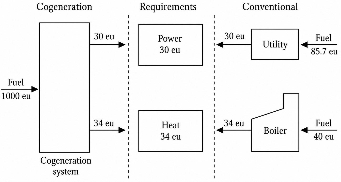
Figure 1 A schematic illustration of the advantages of cogeneration relative to conventional systems.
This overall efficiency also may be found as the sum of the individual efficiencies of the electrical and thermal production. For this example, the cogeneration system has an overall efficiency of
$$\eta _{o}=\frac{30+34}{100}=64%$$
The conventional systems, diagrammed at the right of Figure 1, satisfy the power and thermal needs by the use of an electric utility and a boiler. In this case, the utility is assumed to be able to deliver the 30 energy units of electrical power with a plant efficiency of 35% (which is on the high side for most utilities). This results in a fuel input of 85.7 energy units. The boiler supplies the 34 energy units of heat with an 85% efficiency, which requires a fuel input of 40 energy units. The overall efficiency is, therefore,
$$\eta _{o}=\frac{30+34}{85.7+40}=51%$$
This simple example demonstrates the thermodynamic advantage of a cogeneration system relative to conventional systems for accomplishing the same objectives. In this example, the cogeneration system had an overall efficiency of 64% compared to 51% for the conventional systems. Compared to the conventional systems, this is an absolute increase of 13% and a relative improvement of 25% (based on the 51% efficiency).
To determine the fuel and monetary savings of the cogeneration system relative to the conventional systems, the output power will be assumed to be 50 MW. This is a typical power level for a large university or hospital. The associated thermal output rate for this example would be
$$T=\left ( \frac{34}{30} \right )50MW=56.7MW$$
This may be converted to units of MBtu/h (i.e., million Btu/h)
$$T=56.7MW\times \textrm{3.41 MBtu/h/MW}=\textrm{193.4 MBtu/h}$$
To determine the fuel inputs, the power must be converted to consistent units
$$P=50MW\times \textrm{3.41 MBtu/h/MW}=\textrm{170.7 MBtu/h}$$
Now, the fuel inputs are
$$Fuel_{cogen}=\frac{P+T}{\left ( \eta _{o} \right )_{cogen}}=\frac{170.7+193.4}{0.64}=\textrm{569 MBtu/h}$$
$$Fuel_{conv}=\frac{P+T}{\left ( \eta _{o} \right )_{conv}}=\frac{170.7+193.4}{0.51}=\textrm{714 MBtu/h}$$
The fuel savings is the difference between these two numbers:
$$\textrm{Fuel Savings}=Fuel_{conv}-Fuel_{cogen}=714-569=\textrm{145 MBtu/h}$$
If the plant operates 6,000 h/year (this is about 68% of the time on average—a conservative estimate), then the fuel energy savings per year is 870,000 MBtu. If the fuel price is 8.00 dollars/MBtu, then the monetary saving is 6.96 × 10⁶ dollars per year. Although this is a simple economic analysis, the general trends are relevant.
In summary, the use of cogeneration is an effective way to more efficiently use fuels. The energy released from the fuels is used to both produce electrical power as well as provide useful thermal energy. The savings in energy and money can be substantial, and such systems have been shown to be technically and economically feasible in a wide range of applications.
Cogeneration System Configurations
A cogeneration system may be classified as either a topping-cycle system or a bottoming-cycle system. Figure 2 is a schematic illustration of a topping-cycle system. As shown, a prime mover uses fuel to power an electrical generator to produce electricity. This electricity may be used completely on-site or may be tied into an electrical distribution network for sale to the local utility or other customers. The hot exhaust gases are directed to a heat recovery boiler (HRB) to produce steam or hot water. This steam or hot water is used on-site for process or building heat.
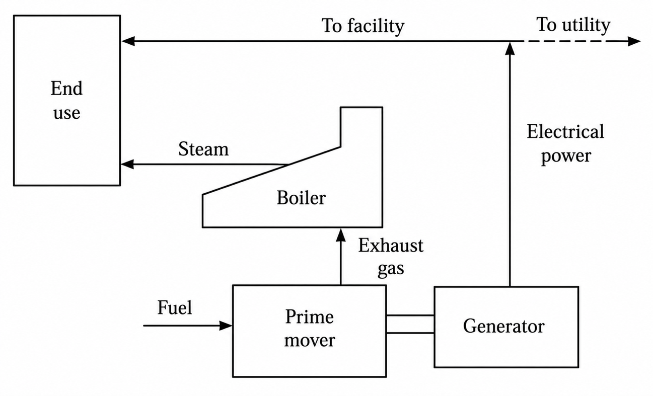
Figure 2 A schematic illustration of a cogeneration topping-cycle system.
This cogeneration system is classified as a topping cycle because the electrical power is first generated at the higher (top) temperatures associated with the fuel combustion process and then the rejected or exhausted energy is used to produce useful thermal energy (such as the steam or hot water in this example).
Figure 3 shows the thermodynamic states of the exhaust gases for this process on a temperature-entropy diagram. For this process, as energy is removed from the combustion gases, the temperature and entropy decrease (since the process involves energy removal). As shown, the top or high-temperature gases are used first to produce the electrical power and then the lower-temperature gases (exhaust) are used to produce useful thermal energy. The majority of cogeneration systems are based on topping cycles.
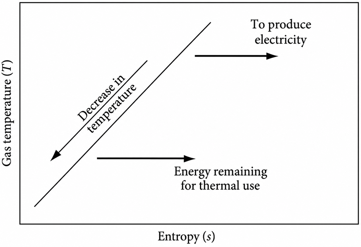
Figure 3 The gas temperature as a function of entropy for a topping-cycle system.
The other classification of cogeneration systems is bottoming cycle systems. Figure 4 is a schematic illustration of a bottoming cycle system. As shown, the high-temperature combustion gases are used first in a high-temperature thermal process (such as high-temperature metal treatment) and then the lower-temperature gases are used in a special low-temperature cycle to produce electrical power.
Figure 5 shows the thermodynamic states of the exhaust gases for this process on a temperature-entropy diagram. After the energy is removed at the high temperatures, the energy available at the bottom or lower temperatures is then used to produce electrical power.
Bottoming-cycle cogeneration systems have fewer applications than topping-cycle systems and must compete with waste heat recovery systems such as feedwater heaters, recuperators, and process heat exchangers.
One of the difficulties with bottoming cycle systems is the low-temperature electrical power producing cycle. One example, depicted in Figure 4, is a low-temperature Rankine cycle. The low-temperature Rankine cycle is a power cycle similar to the conventional steam Rankine cycle, but a special fluid such as an organic substance (like a refrigerant) is used in place of water. This fluid vaporizes at a lower temperature than water, so this cycle is able to utilize the low-temperature energy. These cycles are generally much less efficient than conventional power cycles, often involve special equipment, and use more expensive working fluids.
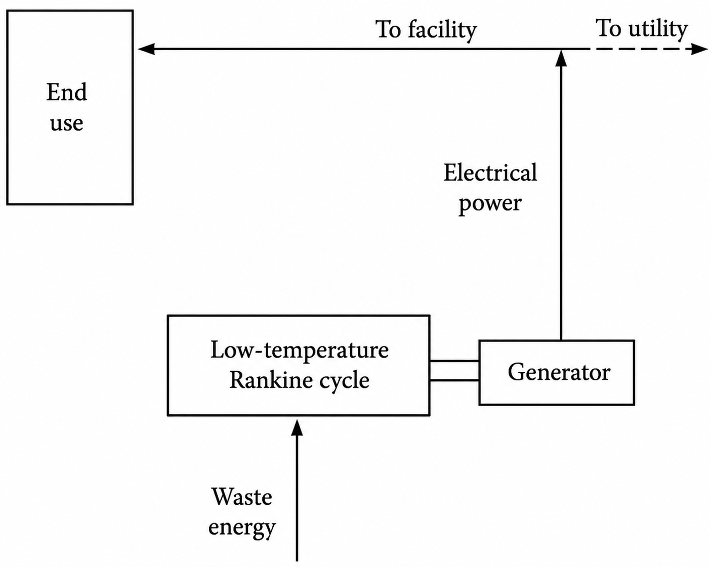
Figure 4 A schematic illustration of a cogeneration bottoming-cycle system.
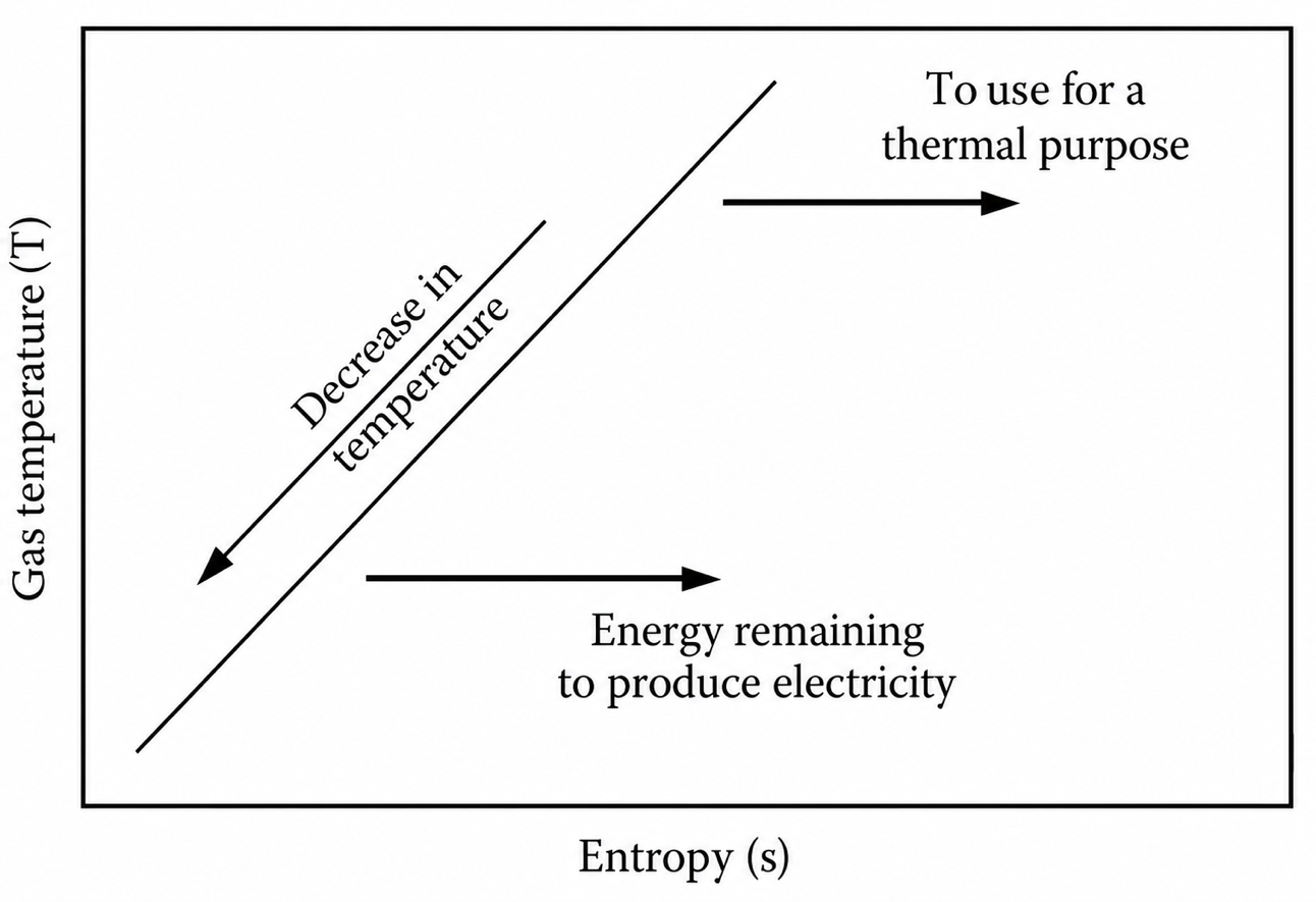
Figure 5 The gas temperature as a function of entropy for a bottoming-cycle system.
Combined Cycles
One power plant configuration that is based on a form of a topping cycle and is widely used in industry and by electrical utilities is known as a combined cycle. Typically in this configuration, a gas turbine is used to generate electricity and the exhaust gas is ducted to a heat recovery steam generator. The steam then is ducted to a steam turbine, which produces additional electricity. Such a combined cycle gas turbine power plant is often denoted as CCGT.
In a cogeneration application, some steam would then need to be used to satisfy a thermal requirement. As might be expected, combined cycles have high power-to-heat ratios and high electrical efficiencies. Current designs have electrical efficiencies of up to 55% depending on the equipment, location, and details of the specific application. These current designs for combined cycle plants result in gas turbine power of between 1.5 and 3.5 times the power obtained from the steam turbine. These plants are most often base load systems operating more than 6000 h/year.
Applications of Cogeneration Systems
Cogeneration systems may involve different types of equipment and may be designed to satisfy specific needs at individual sites. On the other hand, many sites have similar needs and packaged (pre-engineered) cogeneration systems may satisfy these needs and are more economical than custom-engineered systems. The following are examples of cogeneration systems in three different economic sectors.
Cogeneration systems are found in all economic sectors of the world. For convenience, cogeneration systems are often grouped into one of three sectors: (1) industrial, (2) institutional, and (3) commercial. The types and sizes of the cogeneration systems in these sectors overlap to varying degrees, but these sectors are nonetheless convenient for describing various applications of cogeneration.
Industrial Sector
Compared to the other economic sectors, the industrial sector includes the oldest, largest, and greatest number of cogeneration systems. Cogeneration was first used by industry in the early 1900s to supply both electrical and thermal needs in an efficient manner. Many industries have a rich and continuous history of cogeneration applications.
The industrial sector is dominant in cogeneration for several reasons. Industrial facilities often operate continuously, have simultaneous electrical and thermal requirements, and already have a power plant and operating staff. Those industries that are particularly energy intensive, such as the petrochemical and paper and pulp industries, are significant cogenerators. Many of these industries are cogenerating hundreds of megawatts of electrical power at one site. In addition, of course, mid-sized and smaller industries also use cogeneration.
Institutional Sector
The institutional sector includes a wide range of largely not-for-profit enterprises including universities, colleges, other schools, government building complexes, hospitals, military bases, and not-for-profit institutes. Many of these enterprises operate for a majority of the day, if not continuously. Some, such as hospitals, may already have provisions for emergency backup power and have the staff to operate a cogeneration system. Although not as large as the largest industrial cogenerators, a large hospital complex or university may require 50 or more megawatts of cogenerated electrical power.
Figure 6 is a schematic of a cogeneration system installed in 1986 at Rice University in Houston, Texas. As shown, this is a topping-cycle cogeneration system that uses a 3.2 MW gas turbine, a heat recovery steam generator, and two 1000 ton absorption chillers. Because this system was so successful, a second cogeneration system using a combined cycle was installed in 1989. It included a 3.7 MW gas turbine, a 400 kW steam turbine, and a 1500 ton absorption chiller. These two cogeneration systems supply the university with 90% of its electrical power, heating, and cooling requirements.
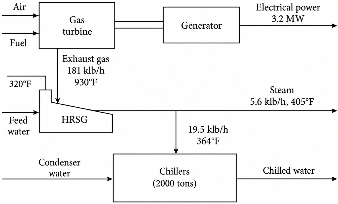
Figure 6 A schematic diagram of the topping-cycle cogeneration system installed in 1986 at Rice University in Houston, Texas.
Commercial Sector
The commercial sector includes a wide range of for-profit enterprises including businesses, hotels, motels, apartment and housing complexes, restaurants, shopping centers, laundries, and laboratories. Generally, this sector includes the smallest cogenerators, and unless the electrical rates are unusually high, the economics are often less favorable than for the other sectors. There has been a greater interest in building cogeneration systems with the push for distributed generation and increased efficiency of electrical generation. Fuel cells are also being used for cogeneration applications in buildings.
Key Takeaways
Cogeneration is one of the most effective methods for improving overall energy utilization by capturing and using waste heat that would otherwise be lost in conventional power generation. By producing electricity and thermal energy from the same fuel source, cogeneration systems can achieve significantly higher overall efficiencies, reduce fuel consumption, and deliver substantial operating cost savings. Topping-cycle and combined-cycle configurations have become widely adopted because they offer reliable, scalable, and economically attractive solutions for facilities with simultaneous power and heating demands. As industries, hospitals, universities, and commercial buildings pursue greater energy efficiency and lower emissions, cogeneration remains a proven technology for enhancing sustainability, resilience, and long-term energy economics.