Ohm Law Calculator
Instantly calculate voltage, current, resistance, or power using Ohm’s Law. Enter any two known electrical values to quickly solve circuit parameters, making it an essential tool for students, technicians, and electrical engineers.
Enter any two known values and press "Calculate" to solve for the others.
Ohm’s Law is a foundational relationship in electrical engineering that links voltage, current, and resistance in conductive materials and ideal resistive components. It states that the current through a conductor is proportional to the applied voltage and inversely proportional to the resistance.
This law is fundamental because it provides a simple, predictive model for how circuits behave. It enables engineers to calculate unknown quantities, design components to meet specifications, and analyze how changes in one parameter affect the others.
In circuit analysis and design, Ohm’s Law is used to size resistors, predict current draw, estimate voltage drops, and interface components safely with power sources. It is the first tool applied in DC analysis and is essential in AC analysis for purely resistive loads or when extended via impedance.
Formal definition: For an ohmic element (one whose V–I characteristic is linear and passes through the origin), the voltage across the element is proportional to the current through it. The constant of proportionality is the resistance.
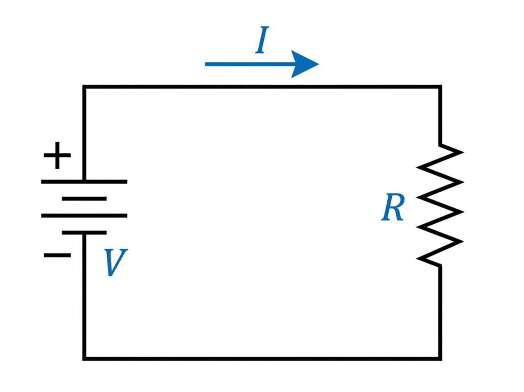
Mathematically: V ∝ I and V = I × R, where R is the resistance.
• Current is directly proportional to voltage (if R is constant).
• Current is inversely proportional to resistance (for a given V).
Historical note: Georg Simon Ohm (1789–1854) experimentally established this relationship in the 1820s, publishing his results in 1827. His work tied electrical measurements to a simple linear model, enabling systematic circuit theory.
Core Electrical Quantities
Voltage (V)
Definition: Electrical potential difference between two points; the work done per unit charge to move a test charge between those points.
Unit: Volt (V) = Joule per Coulomb (J/C).
Physical meaning: A “pressure” that pushes charges through a conductor. Higher voltage tends to drive more current through a given resistance.
Current (I)
Definition: Rate of flow of electric charge past a point or through a surface.
Unit: Ampere (A) = Coulomb per second (C/s).
Electron flow concept: In conductors, mobile electrons drift under an electric field. Conventional current direction is defined as positive charge flow (from higher potential to lower), opposite the electron drift direction.
Resistance (R)
Definition: Opposition to current flow within a material or component.
Unit: Ohm (Ω) = Volt per Ampere (V/A).
Physical interpretation: Arises from collisions and scattering of charge carriers with the lattice/impurities. Higher resistance means less current for the same applied voltage.
Ohm’s Law Formula
Primary form:
V = I × R
Rearranged forms:
I = V / R
R = V / I
When to use each:
• Use V = I × R when you know current and resistance and need the voltage across a component.
• Use I = V / R when you know the applied voltage and resistance and need the current.
• Use R = V / I when you know the voltage across and current through a component and need its resistance.
Any one variable can be found from the other two by algebraic rearrangement.
Ohm’s Law Triangle
The triangle is a mnemonic to remember the three forms without re-deriving. Imagine a triangle divided into two layers: V on the top, I and R at the bottom left and right.
To find a variable, cover it:
• Cover V: I × R remains → V = I × R.
• Cover I: V over R remains → I = V / R.
• Cover R: V over I remains → R = V / I. This visual aids quick recall during calculations and exams.
Relationship Between Voltage, Current, and Resistance
• Voltage vs Current (direct relationship): For constant resistance, doubling voltage doubles current. Intuition: more “electrical pressure” pushes more charge per second.
• Resistance vs Current (inverse relationship): For constant voltage, doubling resistance halves current. Intuition: a narrower “electrical pipe” restricts charge flow.
These relationships are linear only for ohmic elements (constant R over the operating range).
How to Use Ohm’s Law (Step-by-Step Method)
1. Identify known values: Determine which two of V, I, R are given. Include units.
2. Identify the unknown variable: Choose the target (V, I, or R).
3. Select the correct formula: Use the Ohm’s Law triangle or algebra to pick V = I × R, I = V / R, or R = V / I.
4. Substitute values: Insert the numbers with units into the formula.
5. Solve and include units: Compute the result, express with correct SI units and appropriate prefixes (mA, kΩ), and check reasonableness.
Worked Examples
Example 1: Given voltage and resistance → find current
Problem: A 12 V source is applied across a 6 Ω resistor. Find the current.
• Formula: I = V / R
• Substitute: I = 12 V / 6 Ω
• Compute: I = 2 A
• Answer: The current is 2 A.
Example 2: Given voltage and current → find resistance
Problem: A sensor draws 3 mA from a 9 V battery. Find the equivalent resistance.
• Convert units: 3 mA = 0.003 A
• Formula: R = V / I
• Substitute: R = 9 V / 0.003 A
• Compute: R = 3000 Ω = 3.0 kΩ
• Answer: The resistance is 3.0 kΩ.
Example 3: Given current and resistance → find voltage
Problem: A device draws 0.20 A through a 47 Ω resistor. Find the voltage across it.
• Formula: V = I × R
• Substitute: V = 0.20 A × 47 Ω
• Compute: V = 9.4 V
• Answer: The voltage is 9.4 V.
Electrical Power and Ohm’s Law
Electrical power is the rate at which electrical energy is converted to another form (heat, light, mechanical).
Core formulas:
• P = V × I
• Using Ohm’s Law substitutions:
o P = I²R (substitute V = IR into P = VI → P = (IR)I)
o P = V² / R (substitute I = V/R into P = VI → P = V(V/R))
Relationship to Ohm’s Law:
• Power depends on both the voltage across and current through a component.
• For a fixed resistor, increasing current raises power as I², emphasizing the importance of resistor power ratings.
Practical importance:
• Component sizing (choose resistor wattage).
• Thermal management (estimate heat dissipation).
Energy efficiency (minimize unnecessary I²R losses in conductors).
Practical Applications
Circuit design: Determine resistor values for biasing, voltage division, and current limiting (e.g., LED series resistors).
Electrical troubleshooting: Measure two quantities (e.g., V and I) to infer the third (R), identifying faults such as open circuits (very high R) or shorts (very low R).
Load calculations: Predict current draw from supply voltage and load resistance to select fuses and trace widths.
Equipment sizing: Choose power supplies and regulators with adequate current capacity and headroom based on expected I = V/R.
Real-World Examples
Battery and resistor circuit: A 9 V battery feeding a 1 kΩ resistor gives I = 9 V / 1000 Ω = 9 mA. Power in the resistor: P = I²R = (0.009 A)² × 1000 Ω ≈ 0.081 W → use at least a 0.25 W resistor for margin.
Household electrical example (United States 120 V RMS): A 60 W incandescent lamp draws I = P/V ≈ 60 W / 120 V = 0.50 A and has hot-filament resistance R = V²/P ≈ (120 V)² / 60 W = 240 Ω (note: cold resistance is lower; resistance changes with temperature).
Basic industrial example: A 24 V DC control coil rated at 120 Ω draws I = 24 V / 120 Ω = 0.20 A. Power: P = VI = 24 V × 0.20 A = 4.8 W → ensure the supply and wiring handle at least 0.2 A with thermal margin.
Limitations of Ohm’s Law
• Only valid for ohmic materials/components where V–I is linear and passes through the origin over the operating range.
• Not applicable to non-linear devices:
o Diodes (exponential I–V curve).
o Transistors (current controlled by junction/field effects, not by a fixed R).
o Devices like varistors, gas discharge lamps, and LEDs (voltage drops not linearly related to current).
• Temperature effects:
o Resistance of many materials changes with temperature (R = R0[1 + αΔT]). Incandescent filaments and thermistors exhibit strong temperature dependence, invalidating a single constant R across a wide range.
• High-frequency and distributed effects:
o In long conductors or at high frequency, reactance and impedance (Z) dominate; simple R is insufficient. Use V = I × Z with complex quantities.
Common Mistakes
• Mixing values from different parts of the circuit (e.g., using supply voltage across an entire network to compute current through only one branch without considering voltage division).
• Using the incorrect formula or not rearranging properly (e.g., writing R = I/V).
• Ignoring units and SI prefixes, leading to 1000× errors (mA vs A, kΩ vs Ω).
• Misinterpreting circuit conditions (assuming a component sees the full supply voltage when it is actually in a divider or driven by a current source).
• Confusing peak and RMS values in AC calculations for resistive loads.
• Neglecting source internal resistance, causing real voltage drops under load.
Frequently Asked Questions (FAQs)
What is Ohm’s Law in simple terms?
It states that voltage equals current times resistance (V = I × R). If you push harder (higher V) through the same resistance, more current flows.
What are the units of V, I, and R?
Voltage (V) in volts, current (I) in amperes (A), resistance (R) in ohms (Ω).
Is Ohm’s Law valid for AC circuits?
For purely resistive loads, yes, using RMS values: V_RMS = I_RMS × R. For reactive elements, use the generalized form V = I × Z, where Z is complex impedance.
What happens if resistance increases while voltage stays the same?
Current decreases proportionally: I = V / R. Doubling R halves I.
Can Ohm’s Law be used for all materials and devices?
No. It applies to ohmic components with linear V–I behavior. Diodes, transistors, LEDs, and many sensors are non-linear.
How does temperature affect Ohm’s Law calculations?
If R changes significantly with temperature, a single constant R is invalid. Use temperature-dependent resistance models or datasheet curves.