EPC unveils Smallest three-phase GaN motor drive for drones and humanoid robots
Efficient Power Conversion (EPC) unveiled the EPC91132, a 23 mm three-phase GaN motor drive reference design featuring an integrated ePower Stage for compact drones, robotics, and other space-constrained motion systems.
Efficient Power Conversion (EPC) has introduced the EPC91132, a three‑phase brushless DC (BLDC) inverter reference design built around the company’s EPC33110 integrated GaN ePower Stage. Targeting tight mechanical envelopes such as drone propulsion pods and humanoid wrist/hand joints, the design aims to demonstrate how monolithic GaN integration can compress inverter electronics while sustaining high switching speeds and phase current. EPC announced the board on June 9, 2026.
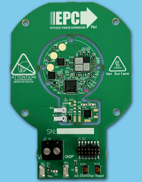
EPC91132 Evaluation Board – Front View
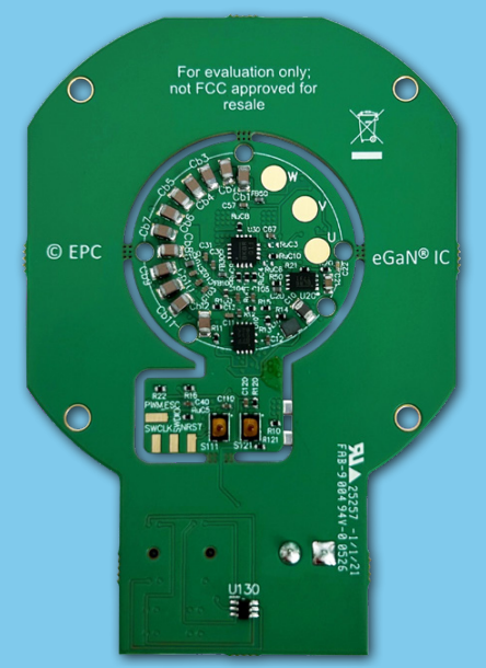
EPC91132 Evaluation Board – Back View
Monolithic GaN ePower Stage at the Core
At the center of the platform is the EPC33110, a 100 V three‑phase ePower Stage that co‑packages three half‑bridges with their high‑/low‑side eGaN FETs, gate drivers, level shifters, and synchronous bootstrap circuitry. Implemented as a GaN monolithic IC and housed in a 6.5 mm × 6 mm thermally enhanced QFN, the device eliminates discrete gate‑driver placement and the associated high‑di/dt loop inductances that typically complicate motor‑drive layouts. The integration reduces component count and routing complexity while enabling higher electrical bandwidth for current control.
From an interface standpoint, the EPC33110 accepts standard 3.3 V or 5 V CMOS logic inputs and uses a single 5 V external bias, simplifying control‑stage power distribution. Typical on‑resistance is listed as 11.7 mΩ (high‑side) and 13 mΩ (low‑side) per phase, supporting operation up to a 100 V DC bus. For compact inverters where copper area and heatsinking are limited, these values—combined with GaN’s low charge—help contain conduction and switching losses at elevated PWM frequencies.
Designed around a 23 mm Motor Footprint
EPC’s reference design adopts a circular “breakout‑ring” printed‑circuit concept: with the outer frame removed, the inverter reduces to a 23 mm diameter disk that can be inserted into small propulsion stacks. The mechanical fit is aligned with 23 mm drone motors, such as the Vertiq 23‑06 form factor, and with rotational modules for humanoid wrists and hands where axial length is tightly constrained. By moving the power stage into the motor cavity, designers can shorten phase leads and improve thermal coupling to airflow from the propeller or joint motion.
EPC91132 implements the ancillary circuits needed for a complete inverter, including regulated housekeeping supplies, DC bus and phase current measurement, over‑current protection, and a magnetic encoder interface for rotor position and speed feedback. Firmware development and diagnostics are supported through a programming connector, and the board exposes an RS‑485 port for real‑time monitoring in system tests or multi‑axis rigs. The input range spans 10 V to 60 V to cover typical lightweight robotics and small UAS battery stacks.
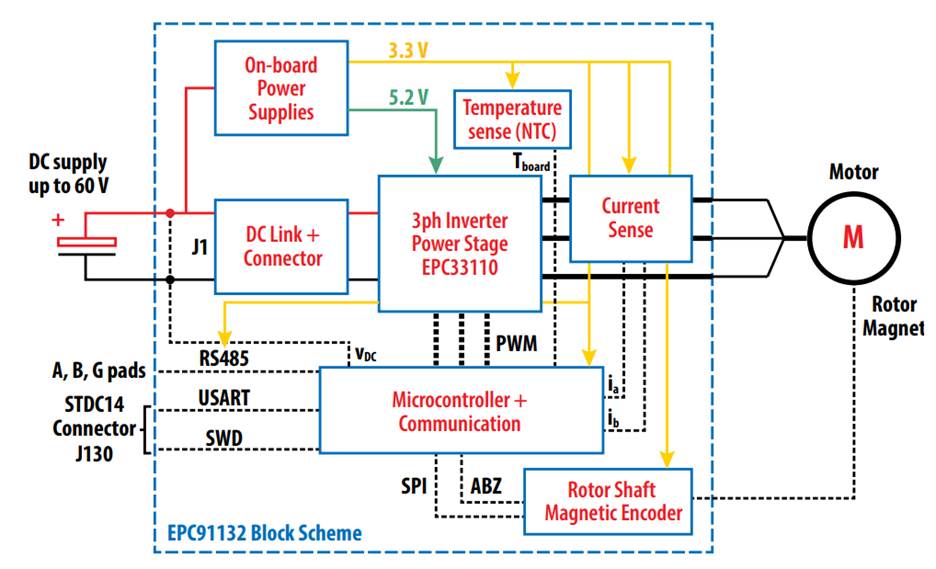
Block diagram overview of the EPC91132 evaluation board
High‑Frequency Operation and Measured Current Capability
The reference platform is positioned to operate well above 100 kHz PWM—an area where GaN’s fast switching and reduced charge directly translate to lower switching losses, smaller passive components, and wider current‑loop bandwidth. For a representative 48 V bus, EPC reports continuous capability of 11 A RMS per phase at a 100 kHz PWM rate, demonstrating current density that is difficult to reach with discrete silicon MOSFET stages in similar footprints. In drone‑motor testing, the company observed modest temperature rise, aided by propeller‑induced airflow across the embedded inverter.
Control and Protection Functions Relevant to Compact Motion Systems
Beyond power stage integration, EPC33110 incorporates features aimed at robust operation in fast‑transient motor drives. Independent high‑ and low‑side inputs per phase allow flexible modulation schemes, while logic lockout prevents shoot‑through when illegal input states occur. The device includes power‑on reset and undervoltage lockouts for critical rails, a fast PWM shutdown pin for immediate fault response, and a standby mode to minimize quiescent draw—useful in battery‑idle states on robots or drones. The QFN’s exposed top and wettable flanks support low thermal resistance to top‑side heatsinking and in‑line optical inspection in production.
Implications for Inverter Layout and EMI
Bringing the drivers and FETs onto a single GaN IC reduces gate‑loop parasitics and the physical separation between power and driver stages, which are common sources of ringing and radiated emissions in high‑dV/dt motor inverters. With three half‑bridges co‑located, phase‑to‑phase symmetry can be improved, easing current‑sharing and simplifying current‑sense placement. The tighter electrical geometry is particularly valuable at 100 kHz‑class PWM where layout‑induced overshoot and common‑mode noise often dictate conservative edge‑rates in silicon designs. The EPC33110 is tuned for motor‑drive switching behavior to address these concerns at the device level.
System Integration and Development Assets
For teams evaluating compact joint or propulsion modules, the EPC91132 arrives as a complete test vehicle: control microcontroller, position sensing, temperature telemetry, and measurement points are already routed to speed bring‑up and loop‑tuning. Documentation includes schematics, bill of materials, Gerber files, and a firmware repository to shorten time to a custom PCB spin. The inverter disk measures 23 mm diameter in its minimal configuration and 55 × 50 mm with the detachable outer frame attached for lab handling and probing.
Availability and Target Applications
The EPC91132 primary use cases include miniature BLDC drives in drones and compact humanoid joints, but the 10–60 V input and 11 A RMS per‑phase capability also map to other low‑voltage motion tasks such as small end‑effectors and gimbals where axial space is limited, and high PWM frequencies are desirable for acoustic reasons. Engineers can adapt the mechanical ring concept to alternate motor footprints once electrical validation is complete.
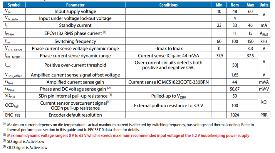
Electrical Specifications of EPC91132
By combining three half‑bridge power stages, high‑speed drivers, and level‑shifting into a single GaN IC and packaging it inside the motor footprint, EPC’s design illustrates a practical route to higher power density and faster control in small BLDC systems.