LCC-HVDC Technology: Converter Operation, Configurations, Reactive Power Control
Learn about the operating principles, converter configurations, reactive power behavior, and key technologies behind line commutated converter (LCC) HVDC systems.
Line commutated converter (LCC) HVDC or classic HVDC is built using thyristors in a current source converter (CSC) topology. Thyristors can be switched on, but need the current to pass through zero in order to switch off. The angle at which the thyristors are switched in is called the firing angle, α.
Figure 1 depicts the basic circuit of a HVDC connection: an AC transformer connected to a six-pulse thyristor bridge. The typical waveform of such a device is shown in Figure 2. Figure 2a shows the waveform for a system without commutation overlap, while in Figure 2b the effect of commutation is shown.
The commutation process is caused by the system inductance and causes a short overlap period during the transfer of the current between two branches of the converter where both branches conduct. This commutation period is expressed as the commutation angle, μ.
In order to reduce harmonics in the AC system, additional harmonic filters are needed. A reduction of the harmonics can also be obtained by utilizing converters with a higher order of pulses: 12-, 18-, or even 24-pulse converters. Most classic HVDC configurations use 12-pulse converters (Figure 1b), which cancels out the 5th, 7th, 17th, 19th,…, (6 ± 1 + k · 12) harmonics.
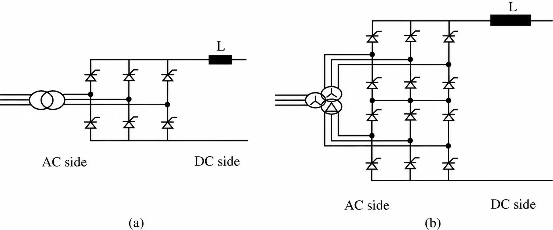
Figure 1 Converter topology for the line commutated converter. (a) Six-pulse LCC converter. (b) Twelve-pulse LCC converter.
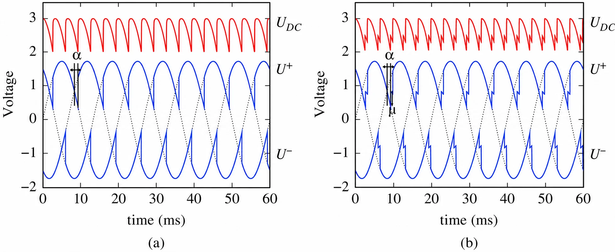
Figure 2 Basic waveforms for the six-pulse thyristor converter. (a) Six-pulse converter waveform, neglecting commutation (α = 27°, μ = 0°). (b) Six-pulse converter waveform, with commutation (α = 27°, μ = 9°).
The transformer of a 12-pulse bridge has a Y–Y–Δ three-winding configuration, or a combination of Y–Y and Y–Δ transformers. Both single-phase and three-phase units are used. The leakage reactance of the transformers is typically 10–18% in order to limit the current during a short-circuit fault of the bridge arm.
In order to reach the required high voltages, several thyristors are placed in series. A single thyristor can block up to 8.5 kV and can carry currents up to 5 kA. There is normally redundancy built in so that a single thyristor failure does not lead to a failure of the entire HVDC link.
The current through the classic HVDC system is always in the same direction. Reversing the power flow is done by changing the polarity of the voltage.
Configurations
Several configurations are possible: monopole, bipole, both with or without ground return, and combinations of these (Figure 3).
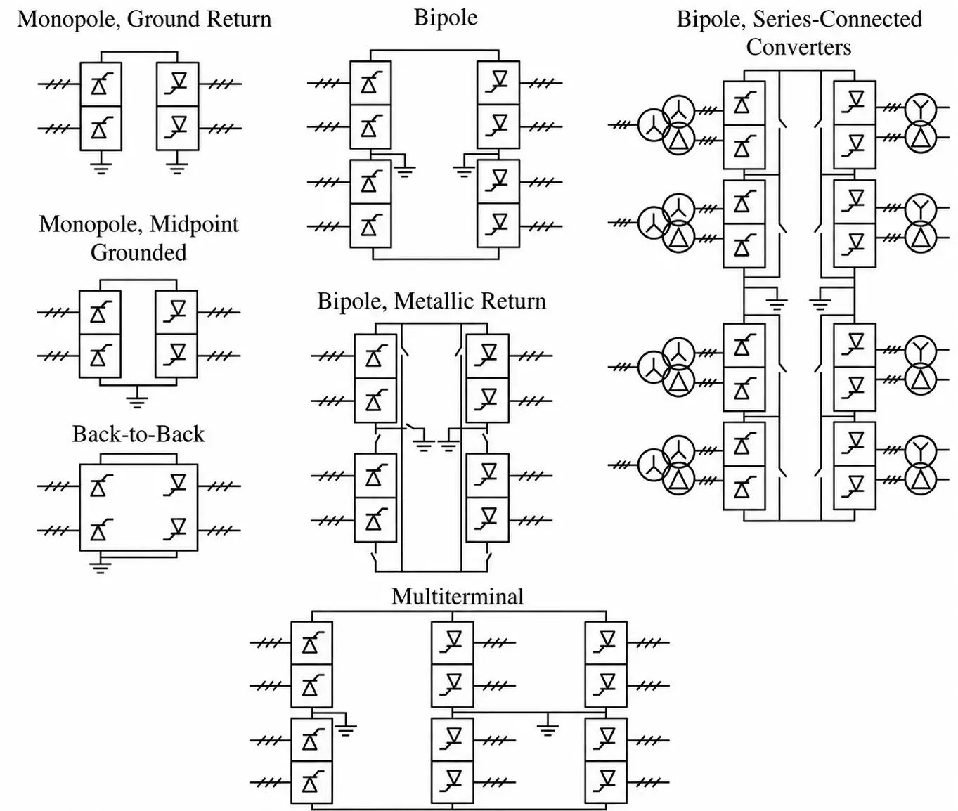
Figure 3 Different configurations for LCC HVDC Systems.
Monopole Configuration
A monopolar link has one conductor at a high DC voltage. The other conductor can use either the ground or sea as the return path or a metallic return wire. The latter can be used when harmonic interference and/or corrosion are an issue. Since the corona effect is more important with positive than with negative voltages, the monopolar link is normally operated with negative polarity in case of overhead lines.
Although systems with a single conductor and earth or sea return are a technically easy and economically beneficial solution, they cannot always be used because of the possible effects of corrosion on metallic pipes in the ground and the possible negative environmental effects on animals, especially fish and boats. However, several of these monopolar configurations are currently in operation, amongst others the recent Baltic cable (connecting the German and Swedish power systems) and the GRITA connection between Italy and Greece.
Systems with a metallic return wire have the advantage that the metallic return only has to be insulated for a very low voltage (I.R). This significantly reduces the need for insulation material around that wire, and hence the cable cost. The Basslink, the connection between Australia and Tasmania which is in use since 2005, is also of the monopolar type with metallic return. Also the connection between Sweden and Poland (SwePol) is of this type.
Bipole Configuration
The bipolar link is the most commonly used topology for modern LCC HVDC connections of high power ratings. Each terminal has two converters of equal rating. Between the converters, the midpoint can be grounded on one or both sides. In case both sides are grounded, there is virtually no current flowing through the ground during normal operation, since the two converters are operated symmetrically.
Bipolar systems require lower voltage ratings for equal power transfer compared to monopolar systems. The monopolar connection requires a pole of double voltage rating, while the bipolar system would require two cables of single voltage rating. A second advantage comes from the ability to use the 50% of the system during maintenance/fault of one module/cable of a bipolar link, by using the ground or a metallic return as return path. For this reason, bipolar systems can be equipped with a metallic return as well. An example of a bipolar connection, without metallic return, is the NorNed link between Norway and the Netherlands.
In a back-to-back connection the two converters are located in close proximity of each other. The typical application is the separation of two independent power systems. These systems are not synchronized or on a different nominal frequency. The DC voltage in the intermediate circuit can be selected freely at HVDC back-to-back stations because of the short conductor length. Because of the short distance, the line resistance is low, and the DC voltage can be kept relatively low, resulting in a smaller valve hall.
Reactive Power Properties of LCC HVDC
Basic LCC-HVDC Reactive Properties
When neglecting the commutation, the required active and reactive power at the terminals of an LCC-HVDC station can be approximated as
$$P=\frac{3\sqrt{2}}{\pi}U_{ac}I_{dc}\cos(\alpha)\ \ \ \ \ (1)$$
$$Q=\frac{3\sqrt{2}}{\pi}U_{ac}I_{dc}\sin(\alpha)\ \ \ \ \ (2)$$
where the firing angle, α, of the rectifier should be replaced with the extinction angle, γ, at the inverter side. When no reactive compensation is used, the reactive power absorbed at the terminals is 0.5 to 0.6 pu at rated active power. This has serious consequences for the control of the voltage at the end terminals, the higher currents (and losses) in the AC grid, and the voltage stability of the system. Therefore, it is often stated that LCC HVDC links can only be inserted when the short-circuit ratio (SCR) is high enough.
Short-Circuit Ratio (SCR)
The SCR is defined as follows:
$$SCR=\frac{\text{Short-circuit MVA of AC system}}{\text{DC converter MW rating}} \ \ \ \ \ (3)$$
in which the nominator of the fraction in (3) is given by (4):
$$SC\,\text{MVA}=\frac{U_{ac}^{2}}{Z_{th}} \ \ \ \ \ (4)$$
where Uac is the commutation bus voltage at rated DC power, and Zth is the Thevenin equivalent impedance of the AC system. Kundur et al. also refer to the effective SCR (ESCR), including the effects of the applications related to the DC link, such as transformers, shunt capacitors, filters, and so on.
$$ESCR=\frac{\text{Short-circuit MVA of AC system}-\text{Reactive power compensation}}{\text{DC converter MW rating}} \ \ \ \ \ (5)$$
The SCR and ESCR can be classified as follows:
- High: SCR ≥ 5 and ESCR ≥ 4.5
- Moderate: 3 < SCR < 5 and 3 < ESCR < 5
- Low: SCR ≤ 3 and ESCR ≤ 2.5
- Very low: SCR ≤ 2 and ESCR ≤ 1.5
The control of the HVDC link has an important impact on its interaction with the AC system. At low and very low (E)SCR, the connection of the LCC-HVDC link becomes difficult and requires specific tuning, or might require additional installations such as a STATCOM. However, specific studies have to be performed in order to assess the full impact.
The HVDC link itself does not contribute significantly to the short-circuit power of the AC power system.
Reactive Power and AC System Strength
Since the AC system has to deliver a significant amount of reactive power, this will have consequences when the system itself is weak. The following problems can arise:
- Dynamic overvoltages in the case of DC transfer interruption
- Voltage stability issues, especially at the inverter side
- Harmonic resonance, as the voltage distortion is higher
- Voltage flicker
Reactive Power Compensation
The traditional solutions to cope with the high reactive power demands at the end terminals of an HVDC link are an adjusted control of the HVDC link, installation of switched capacitors, or dynamic reactive compensation such as SVCs (static VAr compensator), STATCOM (static compensator) or when possible the excitation control of a nearby generator.
Advanced Converters for LCC-HVDC Systems
“New” thyristor-based HVDC systems use different converter topologies, available since the early 1990s. Depending on the manufacturer, several alternative configurations are possible.
The CCC, or capacitor commutated converter, is a configuration used by certain manufacturers, in which a series capacitor is inserted between the transformer and the converter (Figure 4a). Other manufacturers use a different configuration (Figure 4b), with similar results. This solution is called a controlled series capacitor converter (CSCC) and uses a thyristor-controlled series capacitor (TCSC) placed between the power system and the AC transformer.
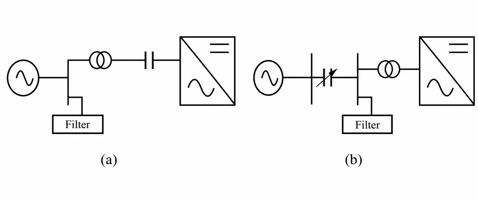
Figure 4 Principal CCC- and CSCC-HVDC topologies schematics. (a) CCC converter module. (b) CSCC converter.
These advanced configurations have the advantage that they can operate in weaker AC grids, and that they can also withstand voltage drops much better. Furthermore, the reactive power requirements are significantly lower.
LCC-HVDC converter reactive power requirements can be significantly limited using these alternative schemes (Figure 5). Also an example of switched capacitors is shown, with the resulting reactive demand, the difference between the conventional converter characteristic, and the switched capacitor characteristic. With the advent of VSC converters, the application of these devices has been limited.
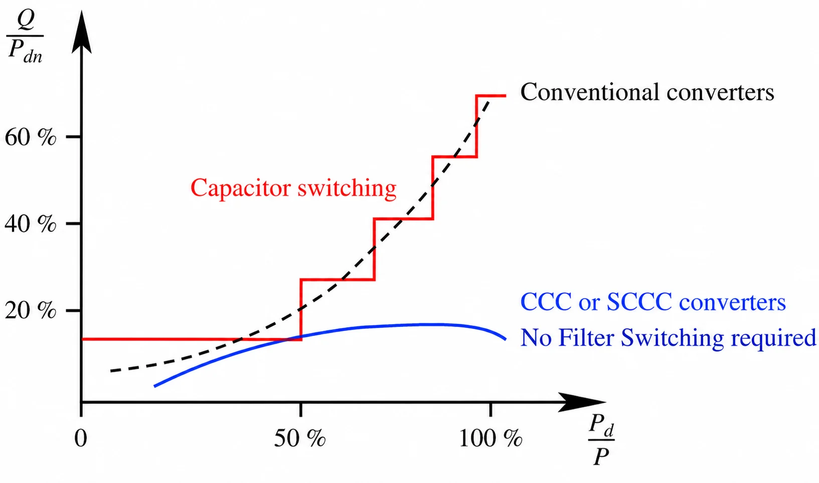
Figure 5 Reactive power demand with different converter topologies.
LCC-HVDC Converter Station Technology
The main components that comprise the HVDC system are the converter station, the transmission medium (cable) and the electrodes. A schematic overview of an LCC-HVDC station is given in Figure 6.
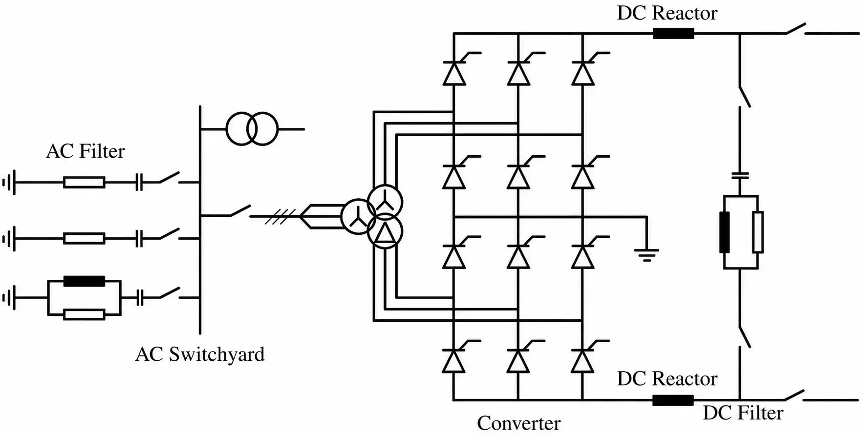
Figure 6 Schematic view of an LCC-HVDC converter station.
Converter Station
Both identical converter stations convert AC to DC and vice versa. The individual components of the converter station are described below.
The thyristor valves have to perform the following tasks:
- Connect AC and DC sides
- Conduct a high current (up to 5 kA)
- Block a high voltage (up to 8.5 kV)
- Control the DC voltage via the firing angle
- Operate fault tolerant and robust
Since the DC voltage is higher than the maximum blocking voltage of a single thyristor, several thyristors are placed in series. Similarly, the current capabilities of a single thyristor can ask for the connection of several thyristors in parallel, which, however, is normally not needed. Normally the thyristors are installed in modules, which are placed in a stack, making maintenance straightforward. The thyristors can be electrically triggered or by using light.
Transformers
Strictly speaking, transformers are not always needed in an HVDC installation. However, they are in practice always used for the following reasons:
- They allow optimizing the DC system voltage independent of the AC transmission system
- Tap-changers can be used to manage the voltage, which can reduce the losses
- Using rectifiers with a higher pulse number is possible
- They Limit the short-circuit current into the valve, working as a smoothing reactor
Depending on the application, different transformers and rectifiers can be used to obtain a techno-economically optimal solution. Because of its size, the choice for a transformer often depends on the available transport means, the location of the substation and its space requirements, or the construction site. The larger HVDC systems mostly make use of multiple single phase units.
Although the principles for LCC-HVDC transformers are quite similar to those of traditional AC transformers, there are several practical aspects of HVDC which cause the transformers to be more complicated, such as oversaturation of the core through DC currents, higher test voltages, and specific arrangements to connect the windings.
Filters and Reactive Compensation
An HVDC link requires several filters and reactive compensation devices. LCC HVDC requires a significant compensation for reactive power. If there are no nearby generators that can compensate for this reactive power, additional capacitors, a SVC, or STATCOM has to be installed.
Furthermore, switching thyristors causes high harmonic distortions on the power system voltage, possibly influencing nearby installations. These harmonics have to be mitigated by additional filters. The DC filter is formed by the DC smoothing reactor which flattens the DC current.
Key Takeaways
LCC-HVDC technology remains one of the most important solutions for high-power bulk electricity transfer due to its proven reliability, high efficiency, and ability to interconnect large power systems. Its thyristor-based converter architecture enables long-distance and high-capacity power exchange, making it widely used for cross-border interconnections, offshore links, and asynchronous grid connections.
Despite challenges such as reactive power demand, harmonic distortion, and dependence on strong AC systems, modern compensation methods and advanced converter topologies have significantly improved system stability and performance.
As power networks continue expanding and integrating renewable energy sources, LCC-HVDC systems continue to play a critical role in improving grid flexibility, power transfer capability, and overall energy infrastructure resilience.