Power System Protection Fundamentals
Learn about protection overlay concepts, including unit and nonunit protection, zoning strategies, and backup schemes for reliable power system operation.
The electrical power system represents the largest electrical circuits devised by human beings; therefore, its protection presents a major challenge. Their role is to carry bulk supplies of electricity from generation, transmit it from the areas of generation to those of application, and finally distribute it to consumers. Through the operation of switchgear, a power system's configuration is inherently variable, and it is continually changed to suit the particular conditions prevailing at any one time.
The power system is designed to operate both efficiently and effectively, in that it is required to provide an economic and a continuous service for both suppliers and consumers of electricity. Economy of operations is expressed in terms of the
- utilization of resources,
- comprising the cost of the power system plant,
- the cost of operating it, and
- the losses incurred in transporting the power.
Continuity of service is expressed in terms of the availability of the system to transport the power away from the generators and to deliver a continuous supply to consumers. Naturally, power system operators and customers want the greatest continuity of service at the lowest cost. There is a natural conflict between these requirements, and a compromise is continually being sought.
An important aspect of the management of a modern power system is the need to ensure that the economy and continuity of service provided by the system are not unduly compromised by a fault on the system or by an abnormal operating condition. This is associated with the protectability of the system and involves the provision of protective gear to detect faults and abnormal operating conditions and to implement appropriate switching actions when they occur.
In an ideal world, power system faults and abnormal operating conditions would not occur, and hence there would be no need for protective gear. Unfortunately, although in the real world, faults in power system plants and abnormal operating conditions rarely arise, if they do occur, the consequences can be dramatic. Therefore, there is a continuous need for protection systems to identify when the system‐affected plant can be disconnected from the network.
The decision‐making process used in protective gears must be accurate in that they must correctly identify the power system plant that is faulted or operating abnormally, such that it, and it alone, is disconnected from the network. This protective gear must also operate with the minimum delay, such that the affected plant can be disconnected from the rest of the power system as quickly as possible, both to minimize potential damage and to maintain system stability.
Nonunit Protection and Unit Protection
Before introducing the concept of the zone of protection, it is necessary to introduce the concept of the nonunit or nonrestricted type of protection and the unit or restricted type protection. Although there are several interesting schemes that exhibit the characteristics of both, all protective devices and schemes can be classified as either nonunit or unit protection.
Nonunit or Nonrestricted Protection
Nonunit protection represents the largest classification of protective devices and includes fuses and all types of overcurrent relays and distance relays. Nonunit protection operates in a standalone mode. It uses information, which is obtained locally, that is, from its relaying point. This point on the power system is defined by the position of the transducers used to obtain information for the protection system. In most cases, it is defined by the location of the current transducers. It is therefore commonly referred to as single‐point protection.
Within the classification of nonunit protection, there are two subclassifications: those protections that use time to discriminate between faults or abnormal operating conditions affecting the protected plant and those affecting adjacent plant, and those protections that use a second source of information obtained at the relaying point.
Nonunit Protection Using Time for Discrimination
For those protections that use time for discrimination, the operation of nonunit protection is not restricted to faults on a particular unit of the plant. Therefore, this type of nonunit protection provides inherent backup protection for a fault on the adjacent plant should the protection associated with that plant fail to disconnect that plant from the network.
Time is frequently used to provide discrimination between the operations of protective gear protecting adjacent parts of the power system network. The protection systems are chosen in such a way that the protection directly associated with the unit of plant operates faster for faults in that plant than the protection associated with the adjacent plant.
Arguably, the simplest type of nonunit protection and the most widely used is the electric fuse. Considering the radial system shown in Figure 1, fuse Bn would carry the fault current caused by short circuit faults on feeder Bn and that the part of the network fed by that feeder and therefore could operate for these faults. For short circuit faults on feeder Cm, however, fuse Cm is chosen such that it operates more quickly than fuse Bn carrying the same fault current, and hence it will disconnect feeder Cm from the source of supply before fuse Bn can operate.
If, however, fuse Cm fails to operate or clear the fault for whatever reason, fuse Bn will eventually operate and clear the fault. For a short circuit fault of feeder Bn and Bn will operate alone, and hence, disconnect feeder Bn and all following feeders from the source of supply. In this scenario, fuse Cm will not be subjected to fault current and hence will not operate.
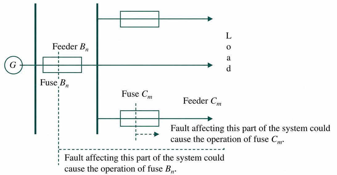
Figure 1 Nonunit protection applied to a radial feeder network.
Nonunit Protection Not Using Time for Discrimination
Protection using a second source of information obtained at the relaying point uses that second input to constrain the reach of the protection such that it will only respond to faults or abnormal operating conditions on a section of the protected plant. Therefore, they will not operate for faults or abnormal operating conditions beyond that reach or affecting adjacent plant.
The best example of this type of protection is the distance relay. This uses voltage to constrain the reach of the protection and hence that part of the power system which is protected. The setting is chosen so that it will not operate for faults or abnormal operating conditions affecting the plant adjacent to that being protected by the protective device.
When the protection is intended to provide enhanced protection and backup protection for part of an adjacent system, time is used to provide discrimination. The time of delay is chosen such that it enables the protective gear, which should clear the fault, to operate first.
The use of stepped distance relays to protect feeder circuits is illustrated in Figure 2, which shows that the relay provides instantaneous protection for part of the protected feeder, time‐delayed protection for the remainder of the protected feeder, and backup protection for the first part of the following feeder.
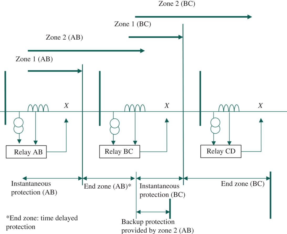
Figure 2 Nonunit protection with constrained reach setting.
Unit or Restricted Protection
Unit or restricted protection represents those types of protective devices that will only respond to faults or abnormal operating conditions on the unit of plant they are protecting and will never operate for faults or abnormal operating conditions on adjacent plant. The best‐known type of unit protection is the current differential protection illustrated in Figure 3.
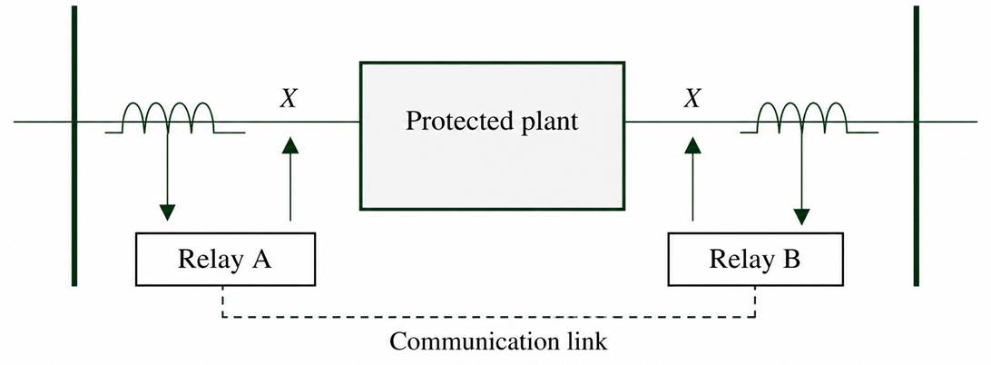
Figure 3 Unit protection.
Unit protection uses information obtained from more than one location in the power supply network and hence has multiple relaying points. When used to protect large units of plant, such as feeder circuits, this leads to the need for communication systems.
Since the protection will only operate for faults or abnormal operating conditions affecting adjacent plant, unit protection provides inherent and absolute discrimination in protecting the adjacent plant. Therefore, there is no need to delay the operation of the protective gear, and the unit protection is instantaneous in operations. But since it will not respond to faults affecting the adjacent plant, it cannot provide backup protection for the protective gear protecting that adjacent plant.
Manageable Units
In order to provide comprehensive protection, an overlay for a power supply system, the system is divided into manageable units, which can be properly protected individually. These units normally consist of a single unit of power system plant together with the switchgear used to connect it or disconnect it from the rest of the power system. Typically, these units of plant may consist of, for example, a transformer, a busbar, and a feeder circuit.
The choice of what equipment constitutes a protected unit can become complicated where different pieces of plant are inherently operated together. The classical example of this is the generator and transformer combination, where the transformer provides the link for the generator to the power system and is therefore dedicated to that generator. In this case, the generator and its transformer may constitute a self‐contained unit of plant and can be treated as a single unit for protection.
The division of a power system into manageable units is illustrated by the network shown in Figure 4. This represents a part of a power supply system being supplied by a local generator and incoming transmission lines, together with a distribution system fed by a step‐down transformer, including subtransmission feeders and local distribution feeders. In order to protect this network, the system has been divided into manageable units that are connected to each other using circuit breakers. In this example, the manageable units of the power system that can be protected individually consist of:
- a generator and its associated transformer
- an incoming transmission line
- one half of the EHV busbar
- a transformer
- a HV busbar
- a subtransmission line
- a distribution busbar
- a distribution feeder
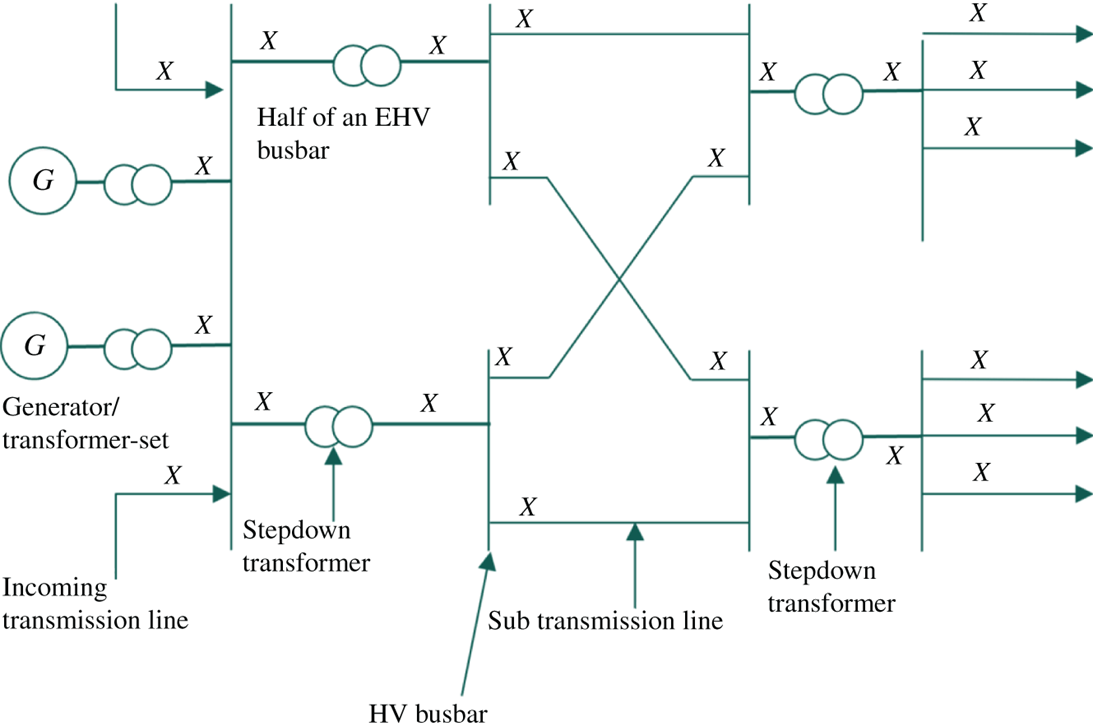
Figure 4 Zones of protection.
Boundaries of the Protection Zones
Each of these manageable units represents a single zone of protection. Taken together, the zones of protection provide a complete overlay for the network, and none of the network is left unprotected. As presented in Figure 4, each of the zones overlaps with the two zones of protection.
The position of the boundaries of the zones of protection depends on the type of protection is used, the positions of the primary transducers, and the circuit breakers. Where the operation is inherently restricted to operate for faults occurring in the zone of protection, that is, the protection is a unit protection, the boundaries are generally defined by the location of current transducers used to provide the protective devices with current information.
The boundary case for an overlapping zone is shown in Figure 5; current transducers are located on each side of the circuit breaker, the first providing information to the protective gear for zone A and the second providing information for the protective gear for zone B. This represents the ideal type of protection scheme since there are no inherent weaknesses in the protection.
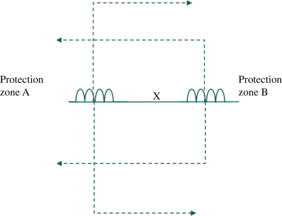
Figure 5 Overlapping zones of protection.
An immediate constraint, frequently applied to protection systems, is the cost of the equipment that can be used. Figure 6 shows two current transducers with two outputs, where a cost constraint is applied. Under these conditions, the transducer output provides information to the protective gear for zones A and B. The two zones of protection do not overlap, and an inherent blind spot is introduced for the protection zone B. Should a fault occur in this blind spot between the current transducer and the circuit breaker, protective gear B will not trip. The fault could continue to be fed from the power system connected to the plant contained in zone B after the protective gear for zone A has operated and opened the breaker.
The conditions described above are not uncommon, and since they produce a weakness in the protection system's coverage of the network, either additional protection is required to detect faults in this blind spot, or different types of protection are required that overcome this weakness. Where additional protection is used to detect faults not cleared by the operation of the protective gear associated with zone A of Figure 6, the protection scheme will generally include breaker failure protection. This provides cover for the blind spot and also protects against the scenario if the circuit breaker fails to clear the fault.
An alternative approach to the protection is to use a nonunit type of protection where the boundary is defined by the poles of the circuit breaker, and time is used to discriminate between the protection system's response to faults in zones A and B. The boundaries of the zones of protection when nonunit protection is used are defined by the relaying point of the protection scheme and the location of the circuit breakers controlled by the protection that protects the adjacent plant. This is shown in Figure 7.
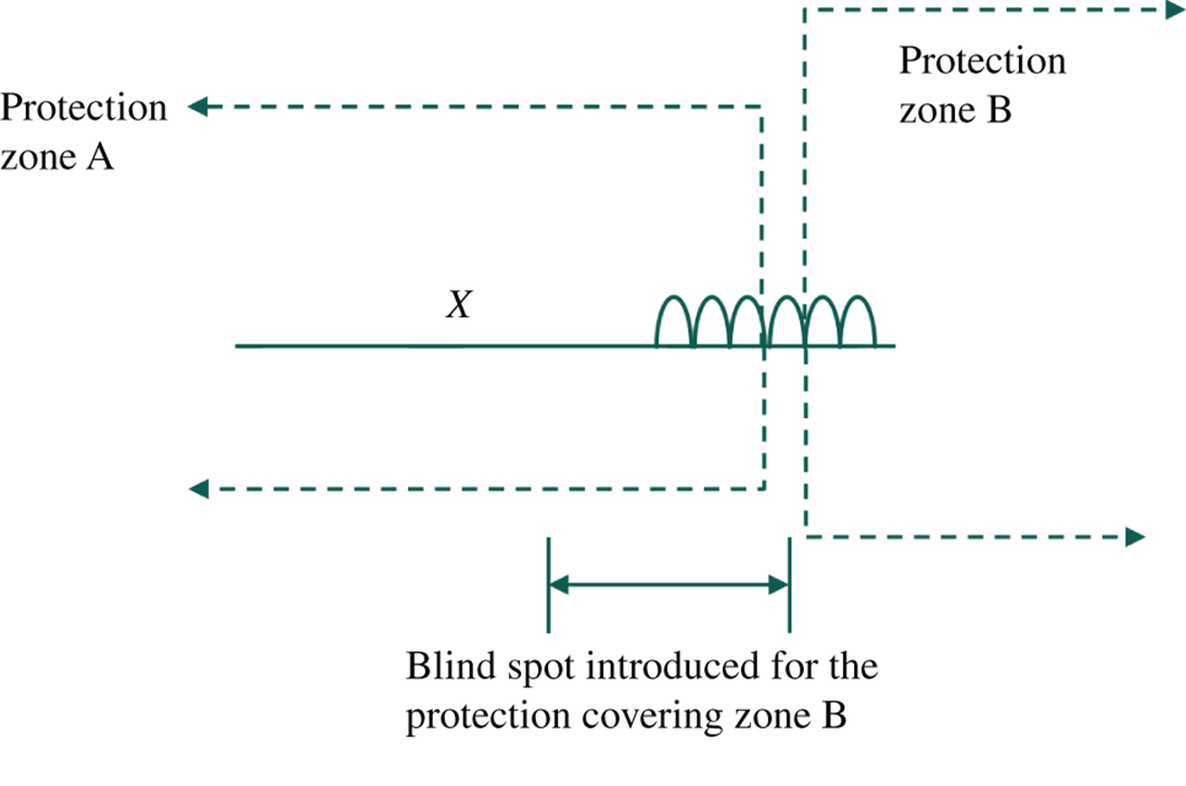
Figure 6 Nonoverlapping zones of protection.
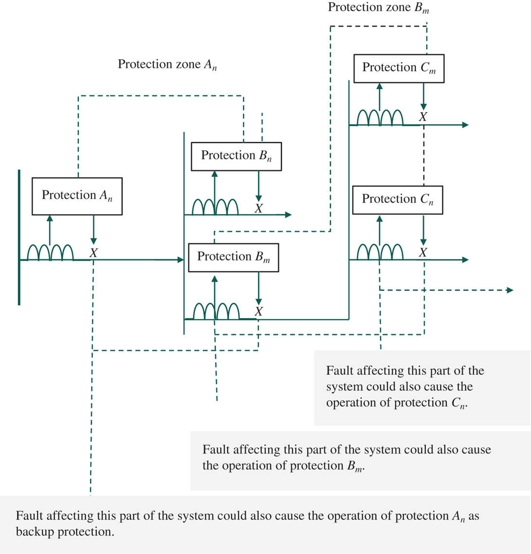
Figure 7 Zones of protection associated with nonunit protection using time for discrimination.
Since the operation of the protection is not restricted to faults within its principal zone of protection, the protective gear associated with zone An of Figure 7 could operate for faults on the following feeder, which is covered by zone Bm. With this type of protection, discrimination between the two sets of protective gear is provided by ensuring that for faults in zone Bm, the protective gear associated with zone An is time delayed with respect to that for zone Bm. The protective gear associated with zone Bm, therefore, has time to clear the fault before the protective gear associated with zone An operates.
The third type of protection zone is provided by the second type of nonunit protection, where the boundaries of the protection zone are defined by the reach setting of the protective system.
The boundaries for the zones of protection associated with a classical stand‐alone distance protection are shown in Figure 8 to ensure that the protective gear associated with zone 1 of Figure 8 does not operate for faults on the following feeder; its reach setting is chosen such that, despite all possible errors, it will not operate for faults affecting the immediate feeder. This reach setting is therefore not protected by the zone 1 elements, and a second zone is required.
This second zone reach is chosen such that it will operate for all major faults affecting the immediate feeder, and as such, it may well operate for faults affecting the following feeder circuit. To provide discrimination between protective gear protecting the immediate feeders and protecting the following feeder, this second zone, zone 2, is time delayed. As a result, faults affecting the end zone of the immediate feeder are also cleared after the time delay. Should the protective gear associated with the following feeder fail to clear a fault in the region covered by zone 2, the zone 2 elements will provide backup protection.
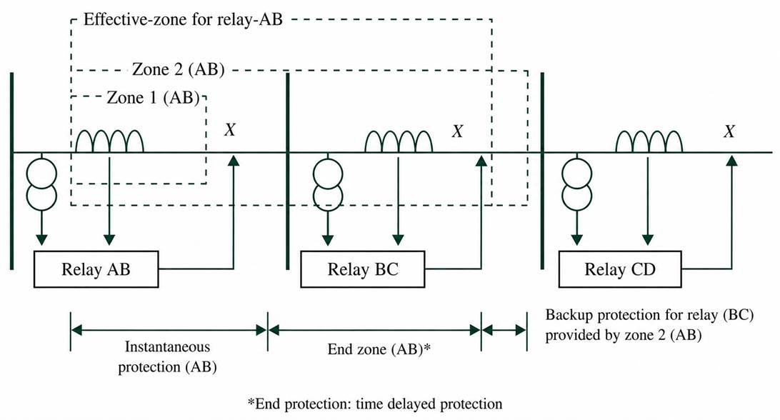
Figure 8 Zones of protection associated with nonunit protection with constrained reach.
Backup Protection
The protection system is a fundamental part of the power supply system, and as such, the power system needs to be protected from failure or abnormal operating conditions in the protective gear as well as the main power system plant.
The inherent backup protection capabilities described above can be used to clear fault or abnormal operating conditions affecting a following unit of the plant if they are not cleared by their own protective gear. An unfortunate weakness of this approach is that in order to disconnect the faulted plant from the network, the normal plant is also disconnected.
Failures in the protective gear can arise from a variety of causes. The failure could be caused by failure in the protection relaying, the primary transducers, the trip control scheme, or the circuit breaker itself. An alternative to depending on the inherent backup protection capabilities of the protective gear associated with the adjacent feeder is to use a second protective system to support the existing protection.
Where the greatest risk of a failure in the protective gear is attributed to the protection relaying, a second relaying system can be used, which operates in parallel with the main system. This is frequently referred to as a primary and secondary protection scheme. If the risk of failure of the protection relaying, the primary transducer, or the trip control scheme is considered unacceptable, a parallel protection system can be justified. This type of scheme is referred to as a dual main scheme of a main A/main B scheme.
Other type of backup protection schemes include trip supervision schemes, which monitor the trip control scheme, and fuse failure protection schemes that are used to monitor three‐phase voltage transformer and either inhibit the protection scheme should one phase of the voltage transformer be lost or switch the protection scheme to a second set of voltage transformers.
Primary and Secondary Protection Schemes
A typical primary and secondary protection scheme is shown in Figure 9. This shows a subtransmission feeder system protected by a distance protection as the primary system and an inverse definite minimum time (IDMT) delay overcurrent protection as the secondary protection. Both sets of protection share the same primary transducers, namely the current transformers.
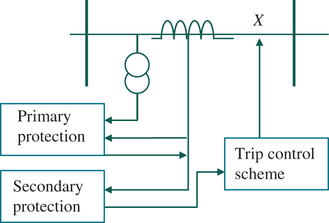
Figure 9 Primary and secondary protection scheme.
Under normal conditions, the primary protection is expected to detect the presence of faults on the protected feeder and to disconnect it from the rest of the network by tripping the circuit breaker. If, however, the primary protection fails to operate due to an internal failure, the overcurrent relay will carry the same fault current and albeit time delay, it will operate and trip the circuit breaker.
In this case, both the primary and the secondary protection will provide inherent backup protection for faults on the system fed by this feeder.
Dual Main Protection Schemes
With a dual main scheme, the primary transducers, the protection relays, and the trip control schemes are duplicated, and both protection systems are chosen to provide the tripping capabilities required by the main protection. This reduces the risk of protection nonoperation to the probability of the circuit breaker only failing. In several cases, the expense of separate transducers is avoided by using a separate outputs from a common transducer.
A typical dual main protection scheme is illustrated in Figure 10. This shows a scheme used to protect a subtransmission scheme, which consists of a distance protection scheme and a current differential scheme. Both schemes provide a comparable level of protection for the feeder, with similar tripping times to initiate circuit breaker operation.
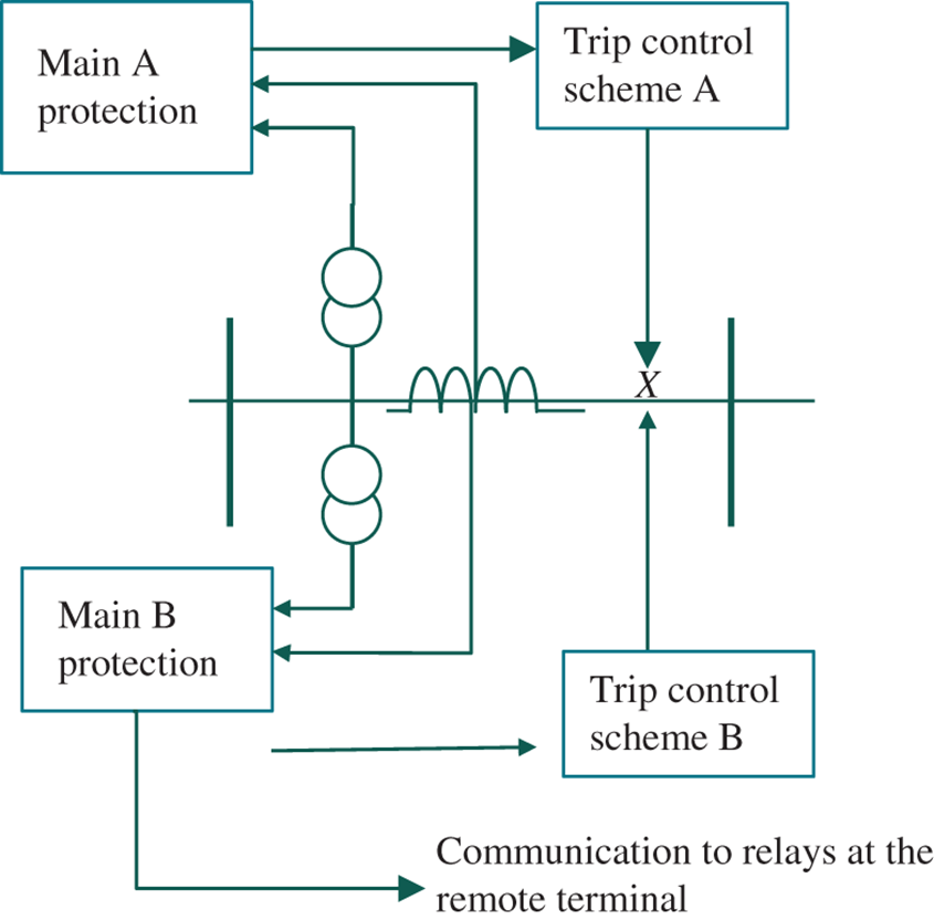
Figure 10 Dual main protection schemes.
Different utilities operate different philosophies for dual main protection, and the variations include:
- Parallel sets of similar relays
- Parallel sets of relays using different operating principles
- Parallel sets of relays form different suppliers
- Parallel sets of relays form different suppliers using different operating principles
Exercise
Considering the protection scheme for the transformer and feeder circuit shown in Figure 11, describe how the scheme would respond to a fault on the transformer and a fault on the feeder given that:
- Current Transformer A (CTA) and Current Transformer B (CTB) have the same ratio.
- CTA has a ratio which is slightly higher than that of CTB, a small mismatch of, say, 10%.
- CTB is omitted.
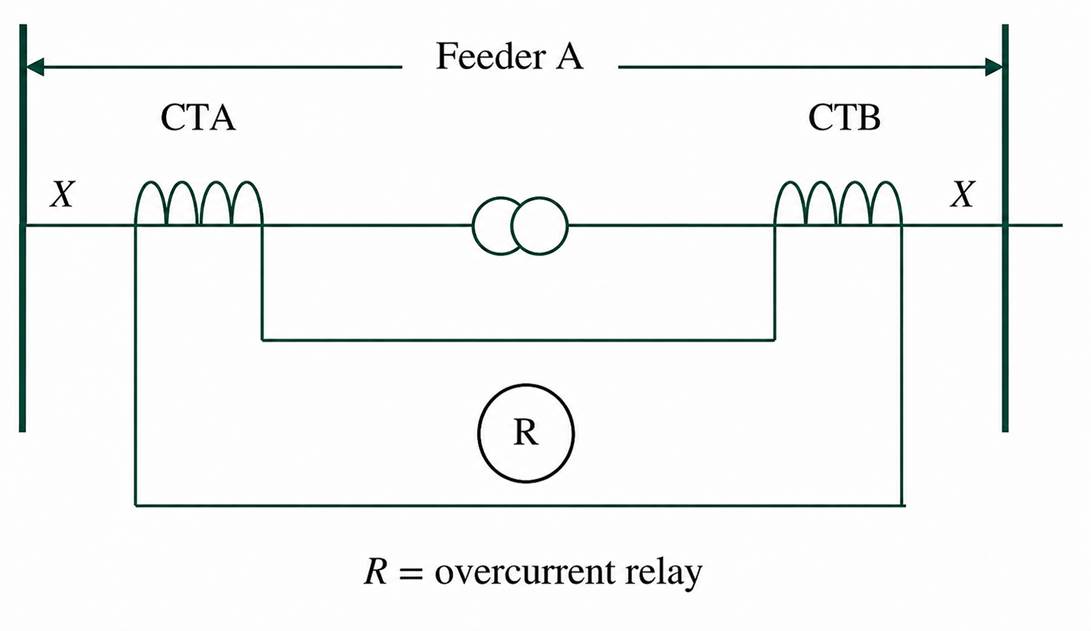
Figure 11 Protection scheme associated with a transformer and feeder circuit.
Solution
1. With the same CT ratio, the relay R would respond to a fault on the transformer but would not see any fault current for a fault on the feeder. This is a classical unit protection scheme.
2. With a small mismatch between the turns ratios of the current transformers CTA and CTB, the protection scheme is described as the “rough balance scheme” and the overcurrent relay is chosen with IDMT characteristics. For a fault on the transformer, the fault current through the relay is the sum of both $I_{CTA}^{'}$ and $I_{CTB}^{'}$; thus the relay has a high driving current, and in the case of an IDMT relay, it would be $I_{CTA}^{'}$ – $I_{CT}^{'}$ , and a low current will pass through the relay, and it will respond more slowly the effective settings for a feeder fault are chosen to grade with any downstream protection.
The scheme is a composite and offers a “high” speed protection for the transformer which has many of the features of unit protection, whereas it offers nonunit type protection for the feeder circuit.
3. If CTB were omitted, the protection scheme would be a classical nonunit protection for the transformer and feeder circuit.
Key Takeaways
Power system protection is built on dividing the network into manageable zones, each safeguarded by dedicated protection schemes to ensure fast and selective fault isolation. Protection methods are broadly classified into unit (restricted) and nonunit (nonrestricted), where unit protection offers precise, instantaneous fault isolation while nonunit protection provides inherent backup through time or reach-based discrimination.
Proper zone boundary design, often with intentional overlap, is critical to avoid blind spots and ensure complete system coverage. To enhance reliability, backup strategies such as primary-secondary schemes and dual main protection are implemented to mitigate failures in relays, transducers, or circuit breakers while maintaining system stability and continuity.