Transformer Characteristics
Inrush Current
When switching ON a transformer, the input or the inrush current is often many times larger than its rated current. This occurs when the switching takes place at the instant the input voltage is at the zero point on its time cycle. This results in a maximum flux that corresponds to a near saturation point on the B-H curve. At this point, the permeability of the magnetic material, the corresponding inductance, and the magnetizing impedance are at a minimum. Thus, the resulting current is at a maximum.
The magnitude and the waveform of the inrush current also depend on the leakage impedance of the transformer, on its magnetization characteristic, on the residual flux, and on the magnitude of the applied voltage at the instant of switching. The current waveform is such as to satisfy KVL. It cannot be accurately described because of the variable and nonlinear circuit characteristics. You can reduce the magnitude of the inrush current by selecting the transformer’s protective circuit breaker with a microprocessor. The microprocessor switches ON the breaker when the supply voltage is zero.
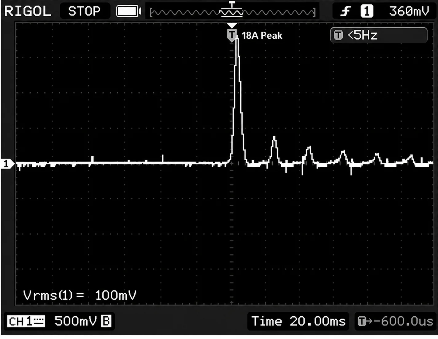
Figure 2-16 The inrush waveform that is captured when power is applied at the main zero crossing point.
The magnitude of the inrush current is comparable to the current that results from external transformer shorts. However, the short-circuit current is of the fundamental frequency, while the magnetizing current has a large content (up to 40%) of the third harmonic.
The magnitude of the inrush current, as per standard industrial practice, is taken as being between 8 and 12 times the rated current of the transformer, and its duration is about 100 milliseconds. As such, it is important in the selection of the upstream protective devices.
Transformer Efficiency
An unloaded transformer when connected to its voltage source, draws only the magnetization current on the primary side, the secondary current being zero. As the load is increased, the primary and secondary currents increase as per the load requirements. The volt amperes and wattage handled by the transformer also increase.
Due to the presence of no-load losses and I2R losses in the windings, a certain amount of electrical energy gets dissipated as heat inside the transformer. This gives rise to the concept of efficiency.
By definition, the efficiency ($\eta$) of a transformer is given by:
$$\eta=\frac{P_{\text{out}}}{P_{\text{in}}}=\frac{P_{\text{in}}-P_{\text{loss}}}{P_{\text{in}}}=1-\frac{P_{\text{loss}}}{P_{\text{in}}} \ \ \ \ \ (2.31)$$
where Pin and Pout correspond, respectively, to the input and output power of the transformer expressed in watts. The power loss (Ploss) is the sum of the core and copper losses of the transformer at the operating conditions under consideration. The copper loss depends on the kVA delivered. When the kVA drawn by the load varies over a 24-hour period, then the so-called 24-hour transformer efficiency may be calculated by using energy instead of power.
Generally speaking, the efficiency of transformers increases with their rating.
Industry continuously tries to minimize core loss by developing higher-quality magnetic materials from which the transformers can be economically manufactured. Where economics permit, copper windings are used instead of aluminum because the aluminum gives higher winding loss (I2R).
The efficiency of the transformer is of primary importance because the cost of energy loss within the transformer over its lifetime is usually greater than that of the transformer itself. Typical transformer losses are shown in Tables 2-1 and 2-2. In the absence of winding condensation, idle transformers should be disconnected from their supply lines; otherwise, their energy consumption, due to core loss, is wasted.
Refer to Figure. 2-17. From basic definitions, we have
$$\text{efficiency}=\frac{\text{output power}}{\text{output power}+\text{losses}} \ \ \ \ \ (2.32)$$
Or
$$\eta=\frac{V_LI_L\cos\theta}{V_LI_L\cos\theta+P_{\text{exc}}+R_eI_L^2} \ \ \ \ \ (2.33)$$
And
$$\eta=\frac{KI_L}{KI_L+P_{\text{exc}}+R_eI_L^2} \ \ \ \ \ (2.34)$$
Where
$$K=V_L\cos\theta \ \ \ \ \ (2.35)$$
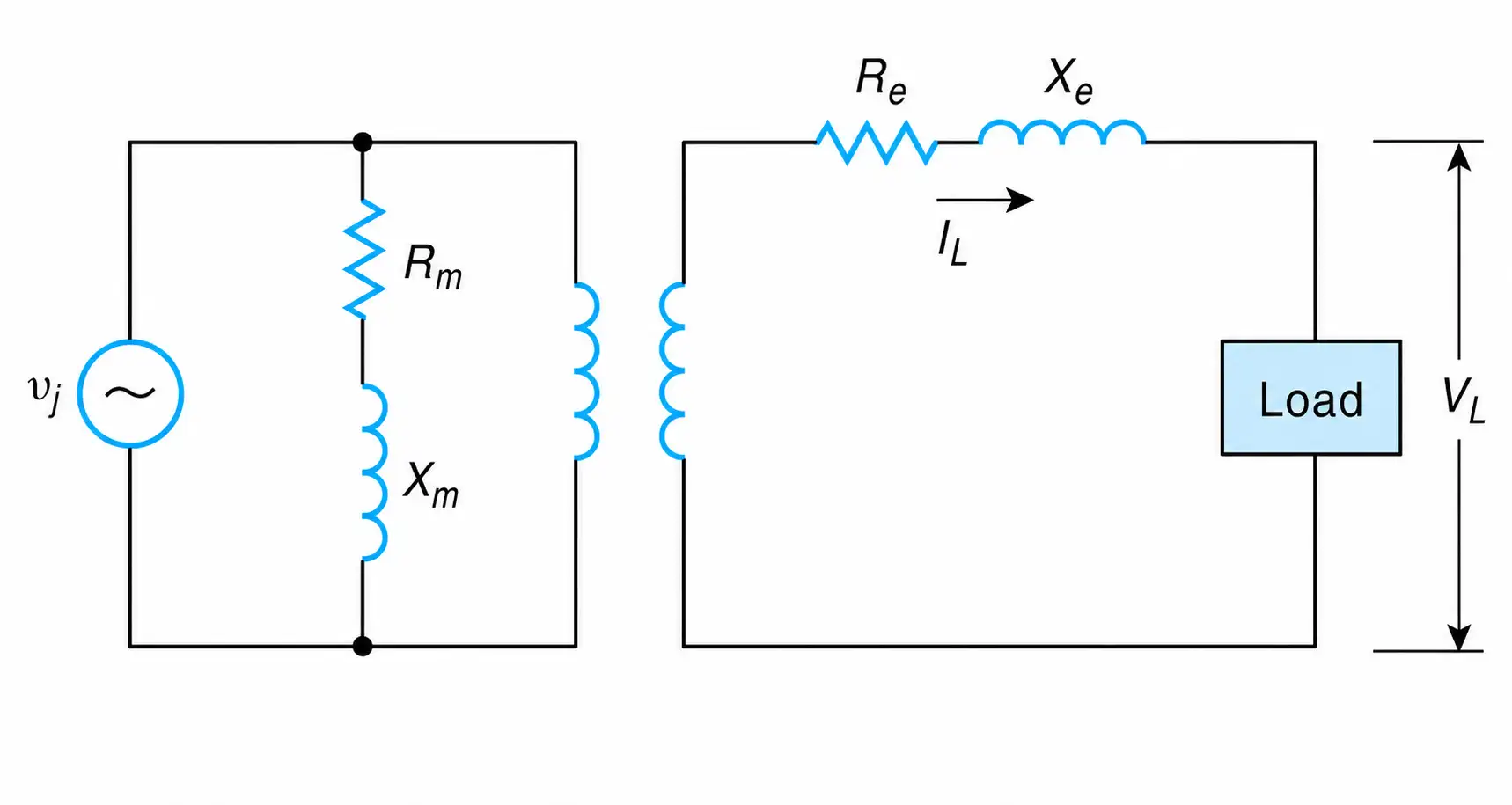
Figure 2-17 Transformer’s equivalent circuit and secondary load.
Taking the derivative of the efficiency with respect to the variable parameter $I_L$ , we obtain
$$\frac{d\eta}{dI_L}=\frac{\left(KI_L+P_{\text{exc}}+R_eI_L^2\right)K-KI_L\left(K+0+2R_eI_L\right)}{\left(KI_L+P_{\text{exc}}+R_eI_L^2\right)^2} \ \ \ \ \ (2.36)$$
Setting the last equation equal to zero gives
$$P_{\text{exc}}=R_eI_L^2 \ \ \ \ \ (2.37)$$
Or
$$P_{\text{exc}}=P_z \ \ \ \ \ (2.38)$$
Thus, the efficiency of a transformer at a constant load power factor is maximum when the iron loss is equal to its winding loss.
A transformer’s efficiency depends on the load current and its power factor. The first condition is obvious, while the second becomes evident when you consider that the primary current, being the vector sum of the exciting current and the component of the load current (see Figure. 2-15(b)), depends on the power factor of the load. The magnitude of the primary current, in turn, controls the primary winding’s copper losses.
When you speak of a transformer’s efficiency, then you must always identify the corresponding current and the power factor.
The variation of efficiency versus load current, as a function of the load current’s power factor, is shown in Figure. 2-18.
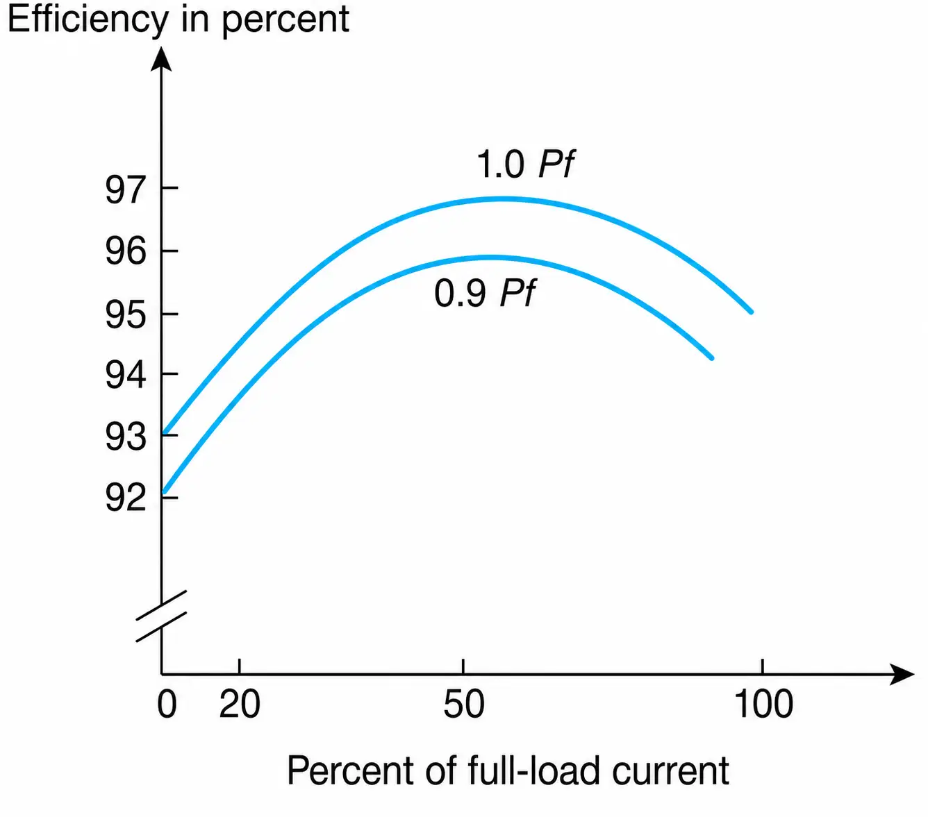
Figure 2-18 Efficiency as a function of load current and power factor.
The variation of iron loss, winding loss, and efficiency versus load current for a 25 kVA transformer is shown in Figure. 2-19.
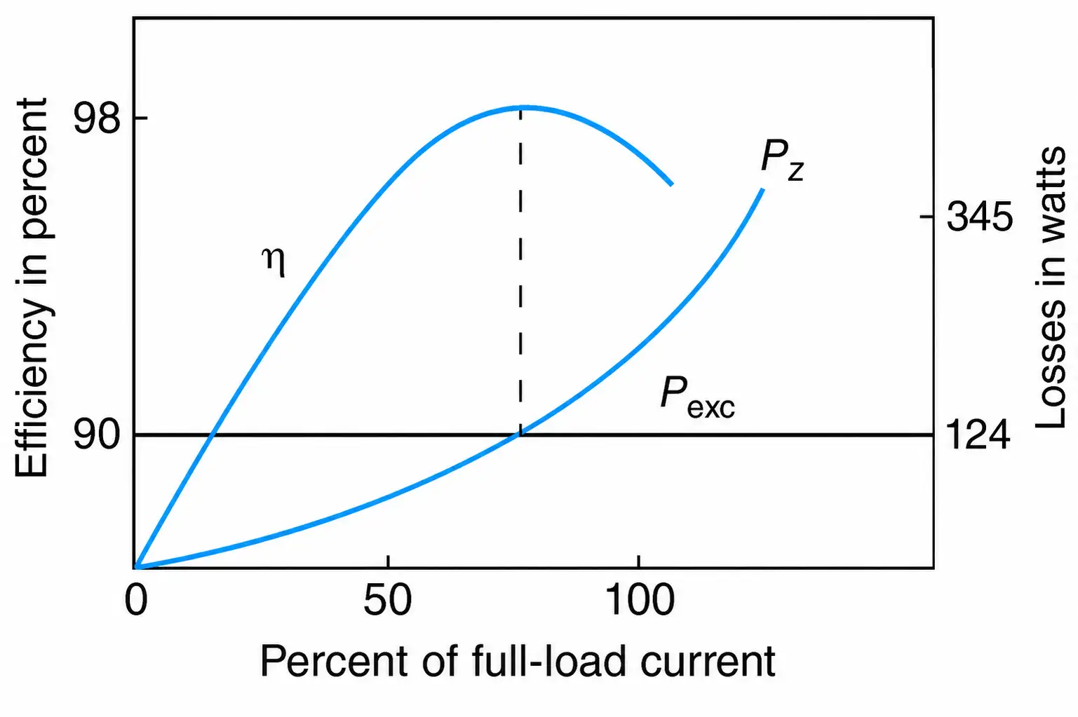
Figure 2-19 Efficiency, iron loss, and winding loss as a function of load current for a 25 kVA, 480-120 V, single-phase transformer.
Voltage Regulation
Voltage regulation is a measure of the change in the magnitude of the output voltage while the load current varies from zero up to its rated value. In mathematical form, regulation is given by
$$\text{Regulation }\%=\frac{|V_{nl}|-|V_{fl}|}{|V_{fl}|}(100) \ \ \ \ \ (2.39)$$
Where $V_{nl}$ and $V_{fl}$ are, respectively, the magnitudes of the voltages at the output terminals of the transformer at no load and at full load. Full-load voltage is also referred to as nameplate voltage, rated voltage, or nominal transformer voltage. No-load voltage can be obtained from the input voltage and the nominal voltage ratio of the transformer. Equation (2.39) can be used for any operating condition. In such cases, the full-load voltage is replaced by its actual value.
Voltage regulation depends on the leakage impedance of the transformer and on the power factor of the load. At a particular value of load power factor and leakage impedance, voltage regulation becomes ideal or zero.
Depending on the power factor of the load, the regulation could be positive or negative. Usually, under steady-state operating conditions, it is less than plus or minus 5% (±5%). Regulation as a function of power factor is shown in Figure. 2-20.
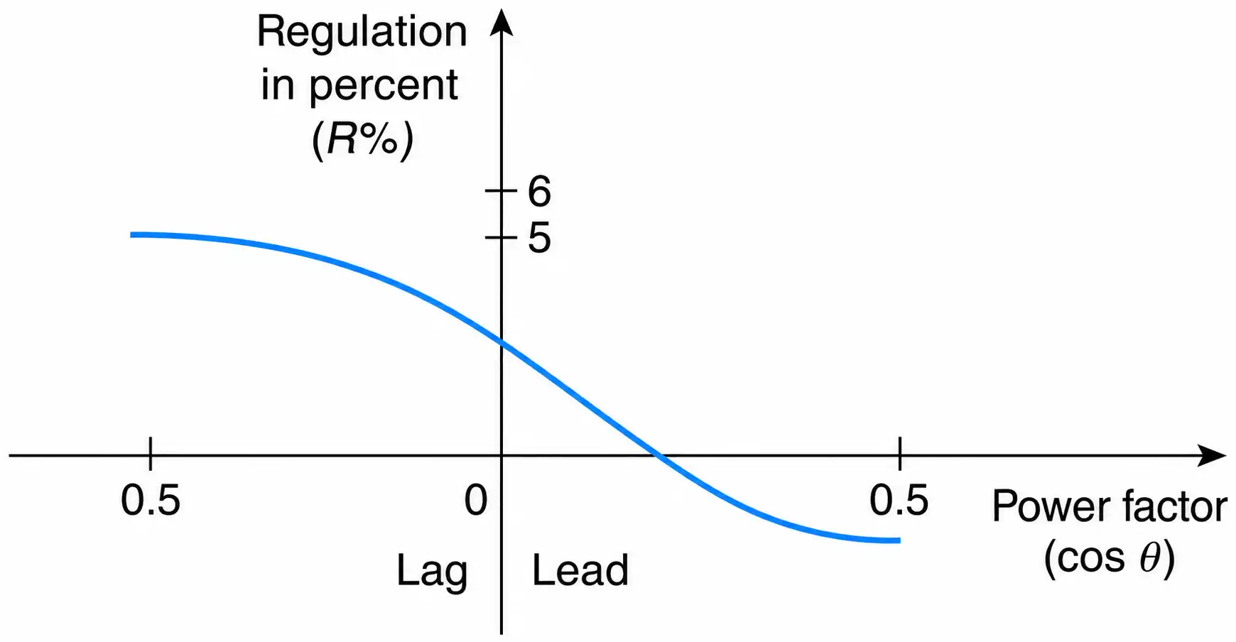
Figure 2-20 Regulation as a function of load power factor for constant rated current.
At leading power factors, regulation is usually negative; that is, the voltage at the secondary terminals of a transformer is larger at full load than it is when the load is disconnected. In such cases, the equipment connected to a transformer’s secondary may be subjected to higher than rated voltages. This may occur when the power-factor-correction capacitor banks remain on the network while the plant operates at a reduced load.
The voltage across the load is of primary importance because many operating characteristics of various pieces of equipment depend on it. For example, a 5% reduction of the rated voltage of an incandescent lamp noticeably reduces its output, and the light appears dimmer. Furthermore, the torque delivered by the motors is reduced by a factor of 10% ($T\alpha V^{2}$). For these reasons, most power distribution transformers, as per manufacturers’ standards, are equipped with “off-load” voltage tap changers through which the voltage can be changed by ±2.5%, or by ±5% in relation to their nominal voltage.
When the voltage is to be changed, the load of the transformer is disconnected and the number of turns of the primary winding is changed according to the requirements.
kVA Rating
The apparent power, or the kVA rating, of a transformer is always inscribed on its nameplate. It indicates the transformer’s transformation capacity in terms of the volt-amperes a transformer is designed to deliver.
The capability of a transformer is limited by heating in the windings (hence, there is a maximum permissible value of sustained current) and by excessively high exciting current and excessive core loss (hence, there is a maximum permissible value for sustained voltage). Rated volt-amperes is the product of rated voltage and nominal current. In normal operation, the input voltage is close to the rated value.
As long as a transformer delivers rated or reduced kVA, it will operate without being overheated. However, when it is cooled, it can dissipate more than nominal heat, and, as a result, it can safely deliver higher-than-rated kVA. For this reason, most substation transformers are equipped with a set of ventilating fans, which enable the transformer’s kVA capacity to be increased proportionally to the ventilation furnished.
A transformer of 1000 kVA supplied with fans, for example, can deliver 1333 kVA without being overheated. Such a transformer is identified as 1000/1333 kVA. Transformers with higher kVA ratings can transform higher magnitudes of voltage and current; that is, their windings have, on a relative basis, larger diameters and more insulation. As a result, the physical size and the cost of a transformer depend on its kVA rating.