Impedance
Physically, the impedance of a circuit represents the opposition of the circuit to the flow of current. The impedance of various apparatuses and machines varies widely. For example, the magnitude of the impedance of a TV set, as seen from the 120 V, 60 Hz voltage source, is several ohms, while the impedance of a large induction machine, as seen from two of its supply wires, is in many cases a fraction of an ohm.
In general, impedance (Z) has a real and a positive or negative imaginary component. That is,
$$Z = R \pm jX\ \text{ohms} \tag{1.66}$$
where R and X are, respectively, the resistance and reactance of the circuit.
The positive reactance ($X=\omega L$) is called inductive, while the negative reactance is called capacitive $X=\frac{1}{\omega C}$. The angular frequency of oscillation (ω) is expressed in rad/s, the inductance (L) in henries, and the capacitance C in farads.
The inverse of the impedance is called admittance (Y), measured in A/V (Amperes per Volt). The admittance has a real part and a negative or positive imaginary part.
That is,
$$\begin{array}{lr}\displaystyle Y = G \pm jB = \frac{1}{Z}\ \text{A/V} & (1.67)\end{array}$$
The real part (G) of the admittance is called conductance, while its imaginary part (B) is called susceptance. The positive and negative signs in the equation represent capacitive and inductive susceptance, respectively. The real part of Y is not necessarily equal to the reciprocal of the real part of Z.
For example, if an impedance is equal to 3 + j4 ohms, then its conductance is, as shown below, $\frac{3}{25}\ \text{A/V}$.
$$Y = \frac{1}{Z} = \frac{1}{3 + j4} = \frac{3 - j4}{(3 + j4)(3 - j4)}$$
$$Y = \frac{3 - j4}{(3^2 + 4^2)} = \frac{3}{25} - j\frac{4}{25}\ \text{A/V}$$
Example 1-6
The R-L circuit shown in Figure 1-21(a) is connected to a 120 V, 60 Hz voltage supply; determine the circuit:
a. Impedance.
b. Current.
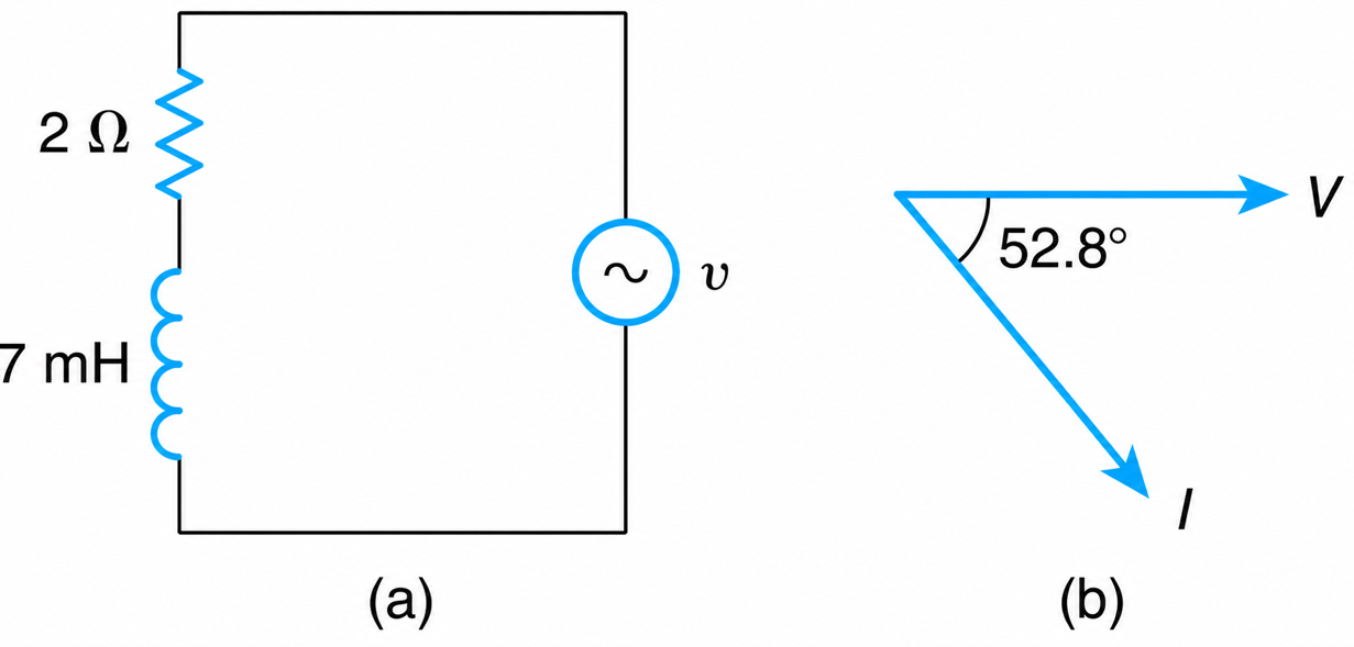
Figure 1-21 Series RL Circuit
Solution
The impedance is
$$Z = R + jX_L = R + j2\pi fL = 2 + j2\pi(60)(7 \times 10^{-3}) = 2 + j2.64$$
$$Z = 3.31 \angle 52.8^\circ\ \Omega$$
The current is
$$I = \frac{V}{Z} = \frac{120 \angle 0}{2 + j2.64}$$
$$I = 36.24 \angle -52.8^\circ\ \text{A}$$
The voltage and current phasors are shown in Figure 1-21(b).