Three-Phase Induction Motor Stator and Rotor
Like all motors, three-phase induction motors transform electrical power into mechanical power by means of a stationary part called the stator and a rotating part called the rotor. Stator or armature windings are housed on the stator, whereas rotor windings are installed on the rotor. For an elementary representation of stator and rotor windings, see Figure 3-1.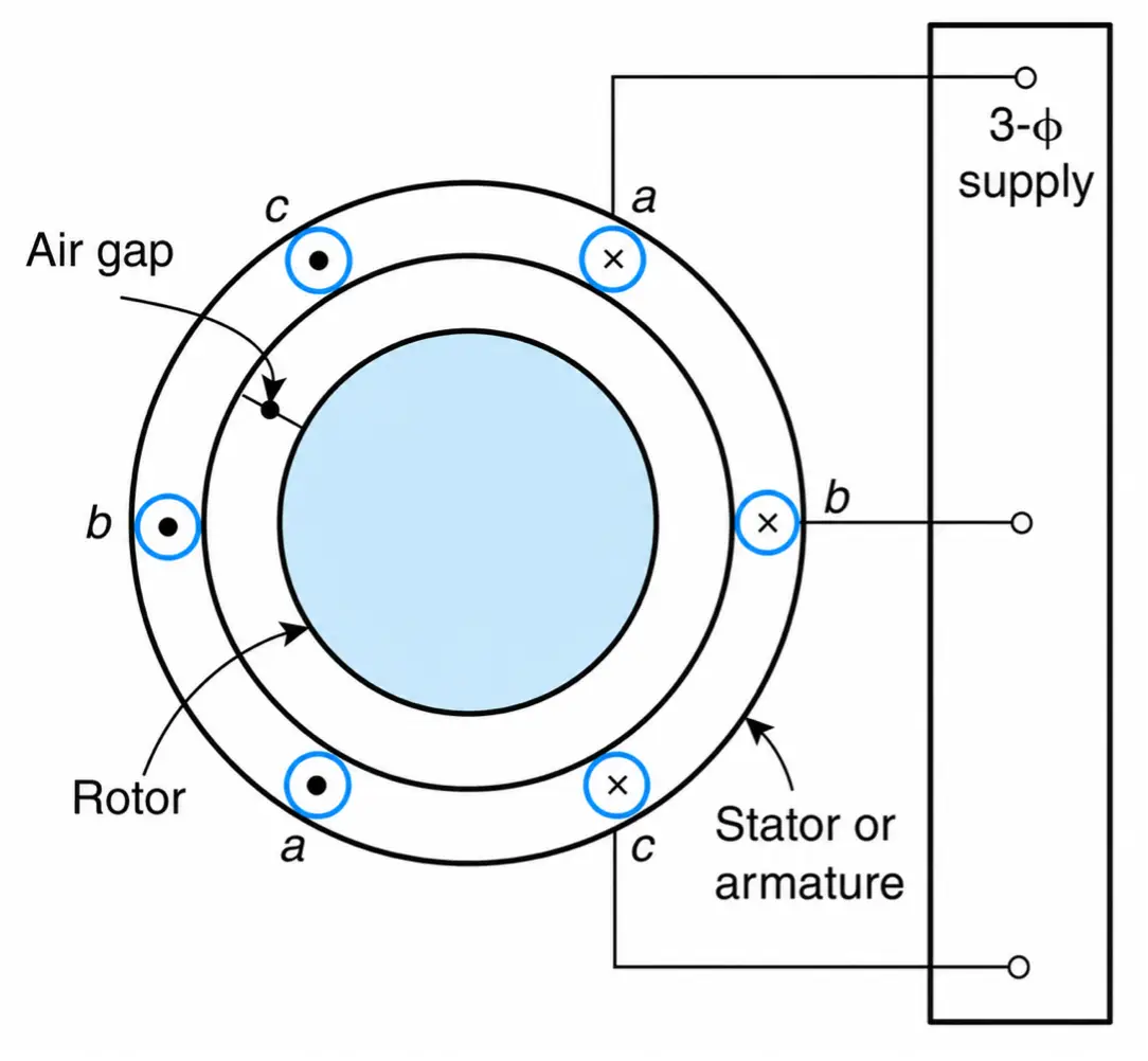
Figure 3-1 An elementary representation of a three-phase induction motor. (In an actual machine, the armature and the field windings are placed in the stator and rotor slots, respectively.)
Stator windings can be either star- or delta-connected. Their main functions are to receive three-phase ac power and to produce a single rotating magnetic field that has an approximately sinusoidal space distribution. This rotating field completes its magnetic path through the stator, two air gaps, and the rotor structure.
Figure 3-2 shows a manufacturer’s picture of an actual armature winding. The stator windings are brought out in a terminal box where they can be connected to a suitable three-phase voltage supply.
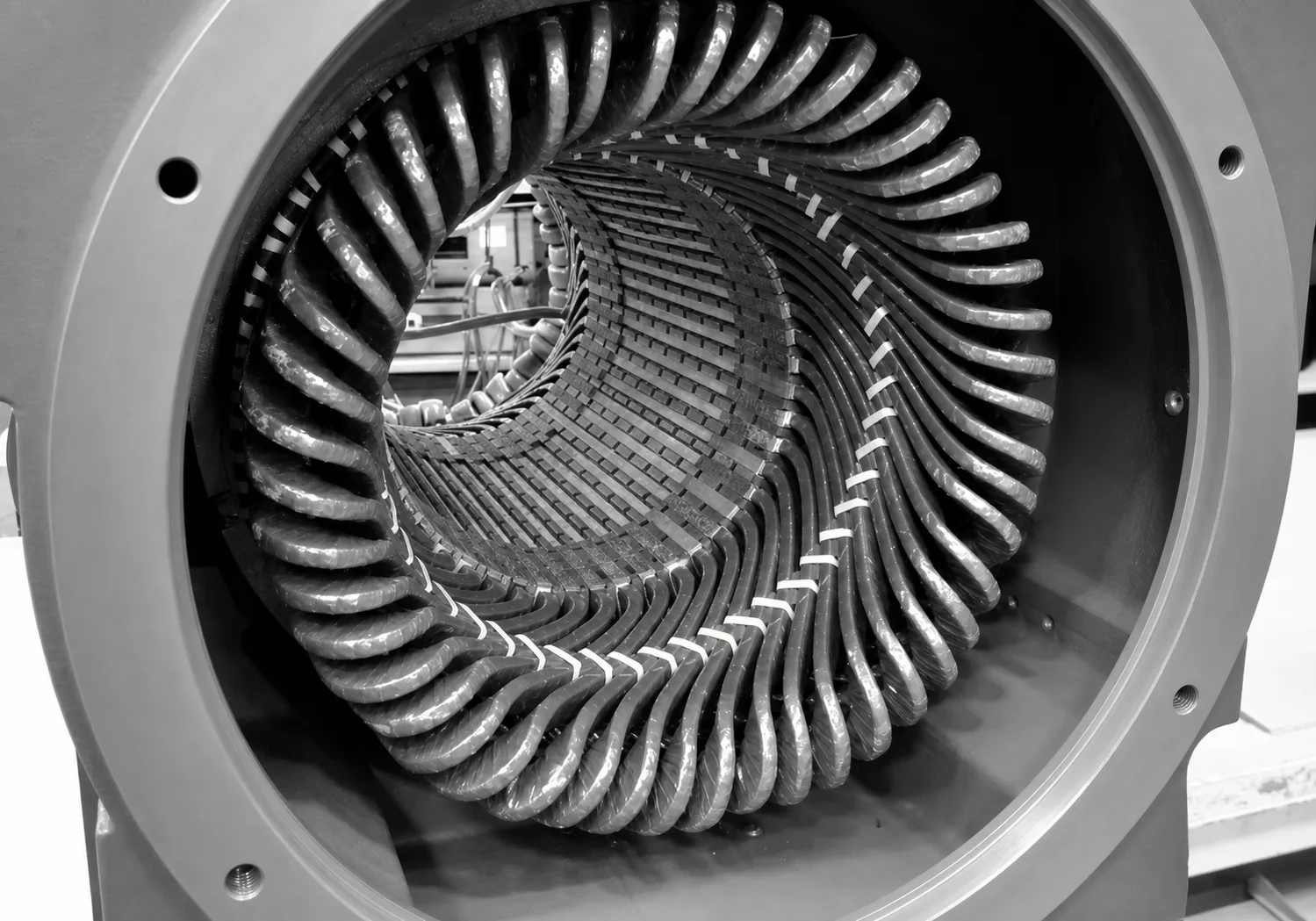
Figure 3-2 Stator windings.
There are two types of rotor windings: the squirrel cage and the wound type. Manufacturer’s pictures of squirrel-cage and wound-rotor windings are shown in Figures 3-3 and 3-4, respectively.
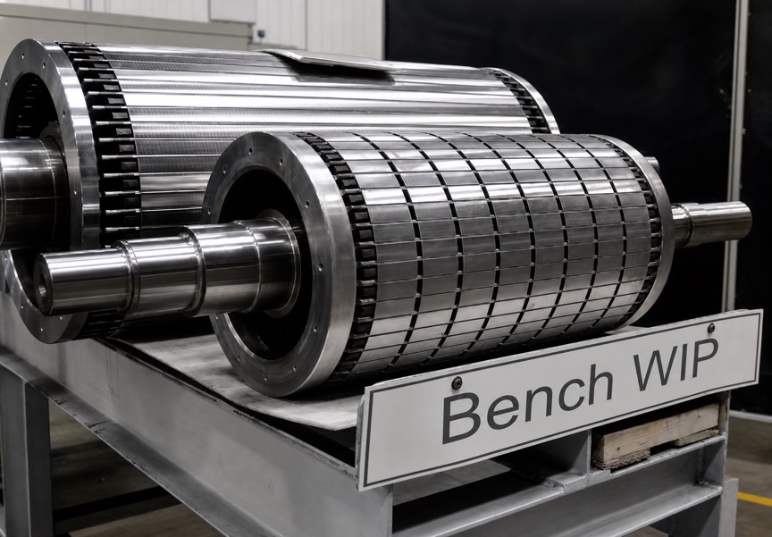
Figure 3-3 Squirrel-cage rotor.
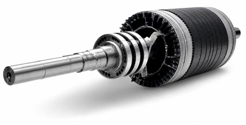
Figure 3-4 Wound-rotor winding.
A squirrel-cage rotor winding is generally made up of bare aluminum bars that are connected at their terminals to shorted end rings. In other words, the rotor windings are always short-circuited regardless of motor operating condition. The rotor bars are not parallel to the rotor axis but are set at a slight skew. This feature reduces mechanical vibrations, making the motor less noisy.
Rotor windings cannot be electrically connected to a circuit outside the rotor. As a result, the rotor resistance is constant, and for a given stator voltage, its torque-speed characteristic is fixed.
In some special designs (for a particular motor application, for instance), the rotor may have double squirrel-cage windings, each with a different resistance. This construction gives higher starting torque, lower starting current, and higher full-load power factor.
A very small percentage of induction machines have a wound rotor. Wound-rotor windings terminate at the slip rings on which the brushes rest. The brushes can then be connected to a three-phase variable resistor, and the resistance of the rotor winding can be externally controlled. This variable resistor controls the torque-speed characteristic of the motor. Figures 3-5 and 3-6 show, respectively, manufacturer’s pictures of three-phase induction motors and rotors.
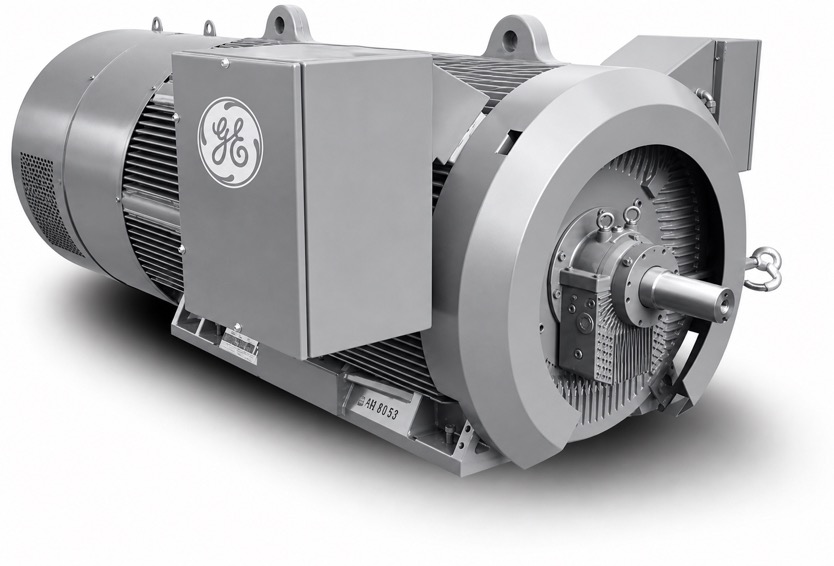
Figure 3-5 Three-phase induction motors: 200 kW, 460 V.
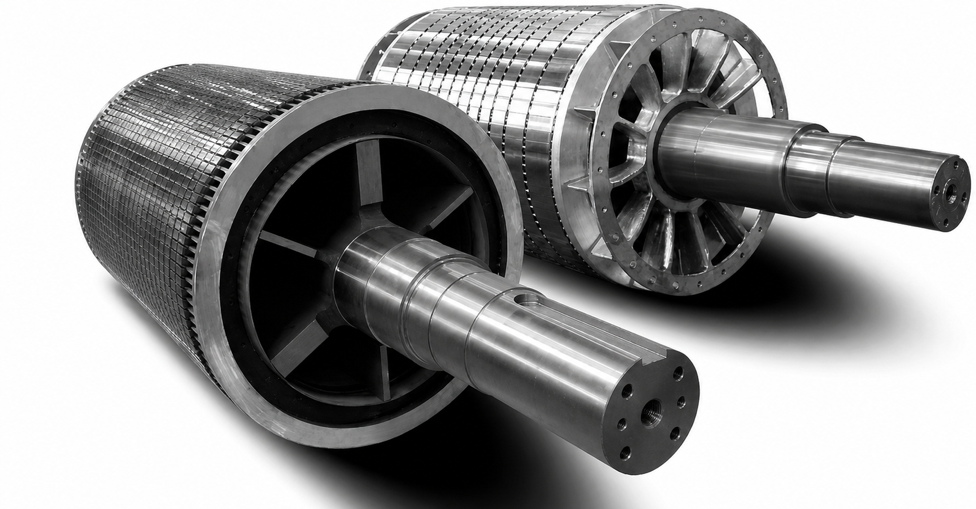
Figure 3-6 Induction motor rotors: 6300 kW, 4160 V.