Power of a Single-Phase Source
In this section, the various forms of power and their units will be discussed, namely, the instantaneous power, the average power, the reactive power, the complex power, and the apparent power. The emphasis will be placed on the average power because of its importance in all power distribution systems. It is for this reason that its governing equation will be derived by using three different methods.
Instantaneous Power
Consider the circuit of Figure 1-31(a). The input voltage waveform is shown in Figure 1-31(b). The instantaneous power (p(t)) drawn by the load, in terms of the instantaneous values of the voltage and current, is given by
$$p(t) = vi \ \ \ \ \ (1.71)$$
where
$$v = V_m\sin\omega t \ \ \ \ \ (1.72)$$
And
$$i = \frac{v}{Z} \ \ \ \ \ (1.73)$$
$$i = \frac{V_m}{|Z|}\sin(\omega t - \theta) \ \ \ \ \ (1.73a)$$
$$i = I_m\sin(\omega t - \theta) \ \ \ \ \ (1.73b)$$
where $\theta$ is the phase angle of the inductive impedance Z.
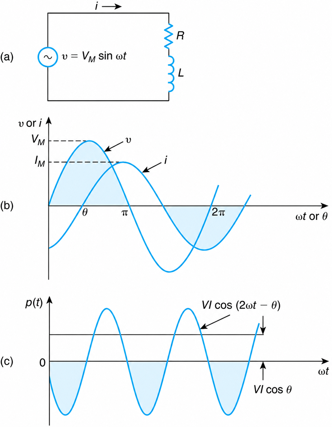
Figure 1-31 (a) R-L circuit. (b) Instantaneous supply voltage and current. (c) Instantaneous power.
Substituting the instantaneous values of the voltage (Equation (1.72)) and current (Equation (1.73b)) into Equation (1.71), we obtain
$$p(t) = V_m I_m \sin\omega t \sin(\omega t - \theta) \ \ \ \ \ (1.74)$$
Replacing the maximum values by their equivalent rms values, and using the identity
$$\sin\alpha \cdot \sin\beta = -\frac{1}{2}\left[\cos(\alpha + \beta) - \cos(\alpha - \beta)\right] \ \ \ \ \ (1.75)$$
we obtain
$$p(t) = VI\cos\theta - VI\cos(2\omega t - \theta) \ \ \ \ \ (1.76)$$
Thus, the instantaneous power drawn from a single-phase network has a constant component $(VI\cos\theta)$ and a pulsating component $(VI\cos(2\omega t - \theta))$ that oscillates at a frequency twice that of the supply voltage.
The variation of instantaneous power as a function of time is shown in Figure 1-31(c).
The constant component is independent of time and is referred to as the average power. It provides the power to motors and heaters while the pulsating power does no work. It produces noise, and is analogous to the foam of a glass of beer that goes back and forth between a bartender and the customer. The latter does not drink it but must pay for it. Similarly, pulsating power although it does no work has to be paid for because of the cost of the cables and equipment associated with its generation and transportation.
Average Power
The average value (P) of the power drawn by an inductive load can also be derived as follows:
$$P = \frac{1}{T}\int_0^T p(t)\,dt \ \ \ \ \ (1.77)$$
$$P = \frac{1}{T}\int_0^T \left(V_m\sin\omega t\right)\left[I_m\sin(\omega t - \theta)\right] d\omega t \ \ \ \ \ (1.77a)$$
$$P = \frac{V_m I_m}{4\pi}\int_0^{2\pi}\left[\cos\theta - \cos(2\omega t - \theta)\right] d\omega t \ \ \ \ \ (1.77b)$$
The second term in the integrand, being a sinusoidal function, has an average value equal to zero. Thus,
$$P = \left(\frac{V_m I_m}{4\pi}\cos\theta\right)\omega t \Big|_0^{2\pi} = \frac{V_m I_m}{2}\cos\theta \ \ \ \ \ (1.77c)$$
Or
$$P = VI\cos\theta \ \ \ \ \ (1.78)$$
$cos\theta$ is known as the power factor.
As seen from the above, the average power consumed by a load is equal to its power factor times the product of the rms value of its voltage and current.
A third method to derive the equation of the average power is to use the following definition of the dot product
$$P = V \cdot I \ \ \ \ \ (1.79)$$
The dot signifies the projection of the current phasor on the axis of voltage. Thus,
$$P = VI\cos\theta \ \ \ \ \ (1.80)$$
The average power is measured in watts and is used to designate the nominal power or the rating of motors and heaters. Average power is often referred to as the real or active or name-plate or output power.
$$1000\ \text{W} = 1\ \text{kW}$$
$$1000\ \text{kW} = 1\ \text{MW}$$
The utilities do not measure the average power consumed by a home. They do, however, measure the power consumed by industries. The power charges are, depending on the utility, 5 to 40% of the total electrical costs.
The utilities measure the average power consumed over 15-minute or 60-minute time intervals and select for billing purposes the monthly highest of these measurements. Their charges are in the range of $\$2 \rightarrow \$15/(\text{kW}/\text{month})$. Rotary meters cannot measure all the power consumed by nonlinear loads (variable speed drives, computers, etc.)
Reactive Power
The reactive power, designated by the letter Q, is measured in Volt × Amps Reactive:
$$Q = \text{VAR} \ \ \ \ \ (1.81)$$
The reactive power is used to designate the nominal or rated reactive power of inductors (Inductive kVAR) and capacitors (capacitive kVAR):
$$1000\ \text{VARs} = 1\ \text{kVAR}$$
$$1000\ \text{kVAR} = 1\ \text{MVAR}$$
The reactive power of a load whose voltage-current phase angle is $\theta$ degrees is
$$Q = VI\sin\theta \ \ \ \ \ (1.82)$$
The inductive loads draw reactive power from the utilities, while the capacitor sends reactive power to them. Another explanation is to say that when a capacitor is connected in parallel to an inductive load, it reduces the current supplied by the utility.
Complex Power
The complex power is designated by the bolted upper-case letter S. It is defined as follows:
$$\mathbf{S} = VI^{*} \ \ \ \ \ (1.83)$$
$$\mathbf{S} = P + jQ \ \ \ \ \ (1.84)$$
$I^{*}$ is the conjugate of the current.
$$\text{When } I = 10\angle -30^\circ\ \text{A, then } I^{*} = 10\angle 30^\circ\ \text{A}. \ \ \ \ \ (1.85)$$
This definition is used to justify the fact that inductive loads draw reactive power (positive) from the utility, while the capacitive loads give reactive power to the utility (negative).
The magnitude of the complex power is called apparent power (S). That is,
$$S = |\mathbf{S}| \ \ \ \ \ (1.86)$$
$$S = VI \ \ \ \ \ (1.87)$$
$$S = \sqrt{P^2 + Q^2} \ \ \ \ \ (1.88)$$
The apparent power is measured in volt-amps (VA) and is used to designate the nominal or the rated power of generators and transformers.
Example 1-10
Prove that the electrical distribution system of a factory can be represented by the parallel combination of a resistor R and an inductive reactance X as follows:
$$R = \frac{V^2}{P}, \qquad X = \frac{V^2}{P\tan\theta}$$
where
- V is the voltage supplied
- P is average power consumed
- $\theta$ is the phase angle between the voltage and the current.
Solution
Refer to Figure 1-32.
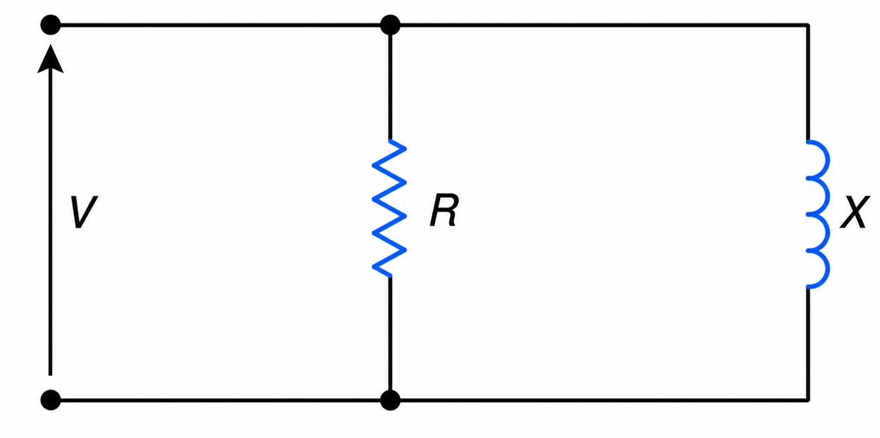
Figure 1-32 Parallel R-X representation of a factory’s inductive load.
$$P = VI\cos\theta$$
$$P = I_R^2 R$$
$$P = \left(\frac{V}{R}\right)^2 R$$
$$P = \frac{V^2}{R}$$
And
$$R = \frac{V^2}{P}$$
$$I_x = \frac{V}{X}$$
$$Q = VI\sin\theta$$
$$Q = VI_x\sin90^\circ$$
$$Q = V\left|\frac{V}{X}\right|$$
$$X = \frac{V^2}{Q} = \frac{V^2}{P\tan\theta}$$
The derived relationships and the load’s circuit representation are of extreme practical importance when evaluating the possible resonant conditions that may arise due to power-factor correction capacitors.