Three-Phase Induction Motor Operation
The operation of three-phase induction motors is based on the generation of a revolving field, the transformer action, and the alignment of the magnetic field axes.
When balanced three-phase currents are injected into the stator windings, they produce a rotating magnetic field that, unless the rotor is revolving at the same speed as the magnetic field, will induce voltages in the rotor windings. This results in rotor current and therefore rotor flux. The magnetic fields of the stator and rotor try to align their magnetic axes—a natural phenomenon—and in so doing, a torque is developed.
Refer to Figure 3-7. The flux of the synchronously rotating stator field ($\phi_{s}$) and the flux of the rotor currents ($\phi_{f}$) combine vectorially to produce the net or resultant flux ($\phi_{R}$) within the structure of the stator and rotor.
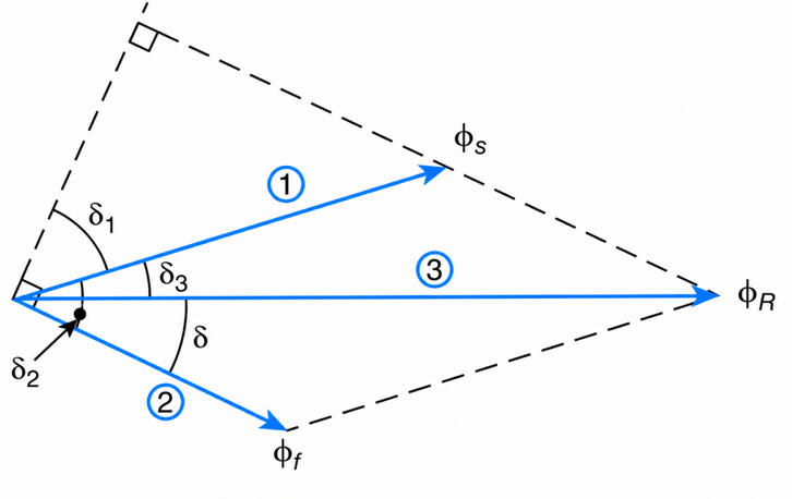
Figure 3-7 Stator and rotor flux in a $3-\phi$ induction machine at standstill.
From Ampere’s Law, the force and the torque (T) developed by two interacting fields are proportional to the product of the strength of the two fields times the sine of the smallest angle between the two fields. Mathematically,
$$T = K\Phi_f\Phi_s\sin\delta_2 \ \ \ \ \ (3.1a)$$
Since
$$\delta_1 + \delta_2 = 90^\circ$$
Then
$$T = K\Phi_f\Phi_s\cos\delta_1 \ \ \ \ \ (3.1b)$$
where the constant of proportionality K is a function of the physical parameters of the machine, and the factor ($\phi_{s}cos\delta_{1}$) is the quadrature component of the stator flux with respect to the rotor field.
From basic trigonometric concepts, we have
$$\Phi_s\cos\delta_1=\Phi_R\cos\left(\delta_1+\delta_3\right) \ \ \ \ \ (3.2)$$
And
$$\Phi_R\cos\left(\delta_1+\delta_3\right)=\Phi_R\sin\delta \ \ \ \ \ (3.3)$$
where $\delta$ is the phase angle between the resultant field and the rotor field. This angle is called the torque angle. From Equations (3.1b), (3.2), and (3.3), we obtain
$$T = K\Phi_f\Phi_R\sin\delta \ \ \ \ \ (3.4)$$
Under ideal conditions, the torque produced in the rotor structure is delivered to the shaft load, while the opposing torque produced in the stator structure is transmitted to the motor’s foundation.
Rotating Magnetic Field
This section analyzes the generation of a rotating field by the stator windings of a $3-\phi$ induction motor and derives formulas that give the strength and speed of the rotating field.
Consider the elementary two-pole, three-phase machine shown in Figure 3-8(a). The dots in the center of the three conductors indicate that the current’s direction is toward the reader, while the crosses indicate that the assumed positive direction of current is away from the reader. The stator windings carry balanced three-phase currents as shown in Figure 3-8(b).
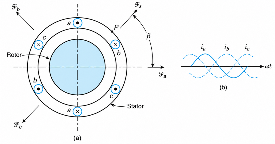
Figure 3-8 Three-phase induction machine: (a) an elementary two-pole induction machine, and (b) balanced three-phase stator currents of sequence ABC.
For a phase sequence ABC, the phase magnetomotive forces (mmf’s) as functions of time are as follows:
$$\mathcal{F}_a = N_A I_{ma}\cos\omega t \ \ \ \ \ (3.5)$$
$$\mathcal{F}_b = N_B I_{mb}\cos\left(\omega t - 120^\circ\right) \ \ \ \ \ (3.6)$$
$$\mathcal{F}_c = N_C I_{mc}\cos\left(\omega t + 120^\circ\right) \ \ \ \ \ (3.7)$$
where Ima, Imb ,and Imc are the maximum values of the phase currents, and NA,NB, and NC are the number of turns of the phase windings. The quantity ω is the angular frequency of oscillation of the stator currents, which by definition is
$$\omega = 2\pi f \quad \textrm{electrical radians per second} \ \ \ \ \ (3.8)$$
where f is the frequency of the stator currents in hertz.
At the instant under consideration, the mmf of phase a coincides with the horizontal axis, as shown in Figure 3-8(a). The directions of phase mmf’s $\mathcal{F}_a$, $\mathcal{F}_b$ , and $\mathcal{F}_c$ are obtained by using the right-hand rule.
The resultant stator mmf ($\mathcal{F}_s$) along an axis at an angle β to the horizontal is found by summing up the projections of the phase mmf’s along this line:
$$\mathcal{F}_s=\mathcal{F}_a\cos\beta+\mathcal{F}_b\cos\left(120^\circ\beta\right)+\mathcal{F}_c\cos\left(-120^\circ-\beta\right)\ \ \ \ \ (3.9)$$
The number of winding turns and the maximum value of the current for each phase are the same. Designating $\mathcal{F}_1$ as the maximum mmf of any one phase, we have
$$\mathcal{F}_1=N_A I_{ma}=N_B I_{mb}=N_C I_{mc}\ \ \ \ \ (3.10)$$
Substituting Equations (3.5), (3.6), (3.7), and (3.10) into Equation (3.9), we obtain
$$\mathcal{F}_s=\mathcal{F}_1\left[\cos\omega t \cos\beta+\cos(\omega t-120^\circ)\cos(120^\circ-\beta)+\cos(\omega t+120^\circ)\cos(-120^\circ-\beta)\right]\ \ \ \ \ (3.11)$$
By use of the identity
$$\cos x \cos y=\frac{1}{2}\cos(x+y)+\frac{1}{2}\cos(x-y)$$
we obtain
$$\mathcal{F}_s=\frac{\mathcal{F}_1}{2}\left[\cos(\omega t+\beta)+\cos(\omega t-\beta)+\cos(\omega t-120^\circ+120^\circ-\beta)+\cos(\omega t-120^\circ-120^\circ+\beta)+\cos(\omega t+120^\circ-120^\circ-\beta)+\cos(\omega t+120^\circ+120^\circ+\beta)\right] \ \ \ \ \ (3.13)$$
Simplifying, we get
$$\mathcal{F}_s=\frac{\mathcal{F}_1}{2}\left[\cos(\omega t+\beta)+\cos(\omega t-\beta)+\cos(\omega t-\beta)+\cos(\omega t+\beta-240^\circ)+\cos(\omega t-\beta)+\cos(\omega t+\beta+240^\circ)\right] \ \ \ \ \ (3.13)$$
The sum of the three underlined terms is equal to zero because these phasors are displaced from each other by 120° and because their magnitudes are equal. Therefore, Equation (3.13) becomes
$$\mathcal{F}_s=\frac{3}{2}\mathcal{F}_1\cos(\omega t-\beta) \ \ \ \ (3.14)$$
Equation (3.14) describes a revolving field that rotates counterclockwise with an angular velocity of ω radians per second. The speed of the revolving field is normally designated by $\omega_{s}$ and is referred to as synchronous speed ($\omega_{s}=\omega$). The flux at a point P that is at $\beta$ degrees to the horizontal will vary sinusoidally with the same frequency as that of the stator currents.
The revolving field may be visualized as being equivalent to the field generated by a permanent magnet rotated about an axis that coincides with the rotor of the machine.
The effective mmf through the stator structure is equal to 1.5 times the mmf produced by one phase alone. The resulting effective flux, at the absence of saturation and rotor current, is directly proportional to this mmf and inversely proportional to the reluctance of the path through which the flux completes its magnetic circuit.
In general, a rotating field of constant amplitude is produced by an m-phase winding wound 2π/m electrical radians apart and excited by balanced m-phase currents. The magnitude of the rotating field is m/2 times the field produced by any one phase, and its speed of rotation is given by Equation (3.8). The direction of rotation of the field depends on the phase sequence of the applied currents. When the phase sequence of the supply voltages is reversed, the direction of rotation of the stator field and the speed of the motor are also reversed.
Mechanical and Electrical Radians
Consider the elementary four-pole machine shown in Figure 3-9(a). Starting at point A and going counterclockwise (2π mechanical radians) around the periphery of the machine’s stator, the following field polarities are encountered: N1S1-S2N2-N3S3-S4N4. This corresponds to two complete electrical cycles (4π electrical radians), as can be seen in Figure 3-9(b).
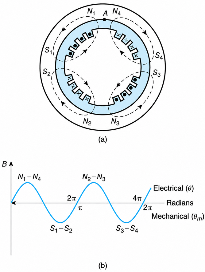
Figure 3-9 (a) Elementary four-pole machine with stator slots and windings omitted; and (b) space distribution of field illustrating the relationship between mechanical (θm) and electrical (θ) radians.
For a four-pole machine, then, one mechanical or physical revolution will correspond to two complete cycles of the field. In general, for a p-pole machine,
$$\theta=\frac{p}{2}\theta_m \ \ \ \ \ (3.15)$$
where θ and θm are the electrical and mechanical radians, respectively.
From Equations (3.8) and (3.15), we get the speed of the rotating field in mechanical radians per second:
$$\omega_m=\frac{2}{p}(2\pi f)=\frac{4\pi f}{p}\quad \textrm{mechanical radians/s} \ \ \ \ \ (3.16)$$
Since one revolution is equivalent to 2π mechanical radians, the speed in revolutions per second (ns) is
$$n_s=2\left ( \frac{f}{p} \right ) \textrm{r/s}\ \ \ \ \ (3.17)$$
The speed in revolutions per minute is
$$n_s=120\left ( \frac{f}{p} \right ) \textrm{r/min} \ \ \ \ \ (3.18)$$
Thus, for a 60 Hz system, the synchronous speed of the stator field will be 3600, 1800, or 1200 r/min when the number of poles is two, four, or six, respectively.
Example 3-1
For a 480 V, $3-\phi$, four-pole, 60 Hz induction motor, determine the speed of the stator field in:
- Electrical radians per second.
- Mechanical radians per second.
- Revolutions per second.
- Revolutions per minute.
Solution
From Equation (3.8),
$$\omega_s = 2\pi(60) = 377\ \textrm{electrical rad/s}$$
From Equation (3.16),
$$\omega_m = 377\left(\frac{2}{4}\right) = 188.5\ \textrm{mechanical rad/s}$$
From Equation (3.17),
$$n_s = 2\left(\frac{60}{4}\right) = 30\ \text(rps)$$
From Equation (3.18),
$$n_s = 120\left(\frac{60}{4}\right) = 1800\ \text(r/min)$$
Slip in Three-Phase Induction Motor
Under normal operating conditions, the rotor rotates in the same direction as the magnetic field of the stator but at a reduced speed. The difference between the synchronous speed of the stator field and the actual rotor speed (na) defines the slip (s) of the motor. The slip of a motor is an important parameter, used extensively in the design and analysis of induction machines. The per-unit value of the slip is given by
$$s=\frac{n_s-n_a}{n_s}\ \ \ \ \ (3.19)$$
Where nS is the synchronous speed of the rotating field, given by Equation (3.18).
To achieve higher efficiency, the majority of three-phase induction motors are designed to operate at a very small slip (usually less than 5%) when delivering rated power.
When three-phase induction machines operate as induction generators, their actual rotor speed is higher than their synchronous speed, and their velocity is in the same direction as the synchronously rotating stator field. Thus, their slip is negative. Induction generators are used to connect small generating stations to large utility networks.
When an induction machine is driven by another motor in such a way that its actual rotor speed is in the direction opposite to that of the synchronously rotating stator field, then na in Equation (3.19) becomes negative, and thus the slip is greater than unity. Induction machines operating at a slip greater than unity are used as frequency and voltage multipliers.
Example 3-2
A 75 kW, 60 Hz, 480 V, 1176 r/min, three-phase induction motor has, at full-load, a power factor of 80 lagging and an efficiency of 0.90. Under rated operating conditions, determine,
a. The magnitude of the current drawn by the motor.
b. The real, reactive, and complex power drawn by the motor.
c. The output torque at full-load.
d. The operating slip.
Solution
a. By definition,
$$\text{Efficiency}=\frac{\textrm{output power}}{\textrm{input power}}$$
In mathematical symbols,
$$\eta=\frac{P_{\text{out}}}{P_{\text{in}}}$$
The output power is 75 kW. The input power is
$$P_{\text{in}}=\sqrt{3}\,V_{L-L}I_L\cos\theta$$
From the above, the magnitude of the line current is
$$I_L=\frac{P_{\text{out}}}{\eta\left(\sqrt{3}V_{L-L}\cos\theta\right)}=\frac{75{,}000}{0.90\left(\sqrt{3}(480)(0.80)\right)}=125.29\ \text{A}$$
The current phasor is shown in Figure 3-10(a).
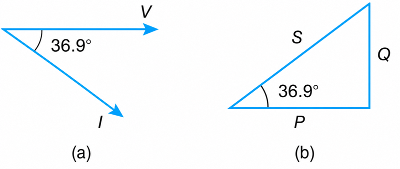
Figure 3-10 Current Phasor and Power Triangle
b. The real or consumed power is
$$P_{\text{in}}=\sqrt{3}V_{L-L}I_L\cos\theta=\sqrt{3}(480)(125.29)(0.80)=83.33\ \text{kW}$$
Or
$$P_{\text{in}}=\frac{P_{\text{out}}}{\eta}=\frac{75}{0.9}=83.33\ \text{kW}$$
The reactive power is
$$Q=\sqrt{3}V_{L-L}I_L\sin\theta=\sqrt{3}(480)(125.29)\sin(36.9^\circ)=62.5\ \text{kVAR}$$
Or
$$Q=P\tan\theta=83.33\tan(36.9^\circ)=62.5\ \text{kVAR}$$
The complex power is
$$S=\sqrt{3}\,V_{L-L}I^{*}$$
$$=\sqrt(3)(480)(125.29\angle 36.9^\circ)=104.17\angle 36.9^\circ\ \text(kVA)$$
Alternatively,
$$S=P+jQ$$
$$=83.33+j62.5=104.17\angle 36.9^\circ\ \text(kVA)$$
The motor’s power triangle is shown in Figure 3-10(b).
c. The full-load output torque is
$$T=\frac{\text{power}}{\text{speed}}=\frac{75{,}000}{1176\left(\frac{2\pi}{60}\right)}=609\ \text{N}\cdot\text{m}$$
d. By inspection of the given data, it can be determined that the motor’s synchronous speed is 1200 r/min. The operating slip is
$$s=\frac{n_s-n_a}{n_s}=\frac{1200-1176}{1200}=0.02\ \text{pu}$$