Principles of Electric Circuits
This section explains Ohm’s and Kirchhoff’s laws and their application in solving problems of electric circuits.
Ohm’s Law
According to the generalized Ohm’s law, the current that will flow in an electric circuit is given by the ratio of the circuit potential divided by the circuit impedance. Referring to Figure 1-24, we have
$$i = \frac{v}{Z} \tag{1.68}$$
where i, v, and Z are, respectively, the current, voltage, and impedance of the circuit in phasor form.
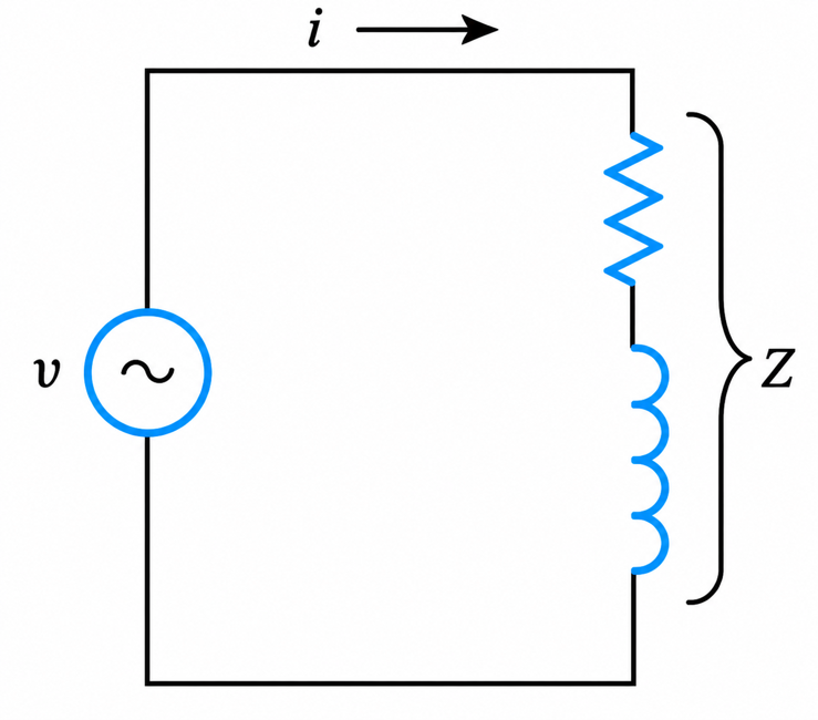
Figure 1-24 RL Series Circuit
The impedance is a characteristic of the circuit and in electric machines—depending on the type of machine and the operating condition—may be a variable. The current through an electric circuit driven by a zero-impedance voltage source can be increased to infinity when the circuit impedance is shorted.
In the following example, Ohm’s law is used to derive general expressions for the voltage across two series resistors as a function of the supply voltage (the voltage-divider concept) and the current through two parallel resistors as a function of the supply current (the current-divider concept). The derived mathematical equations simplify the solution of many problems in electric and magnetic circuits.
Example 1-7
Referring to the circuit of Figure 1-25, prove the following:
a. $V_x = V\frac{R_b}{R_2}$
b. $I_1 = I\frac{R_2}{R_1 + R_2}$ and $I_2 = I\frac{R_1}{R_1 + R_2}$
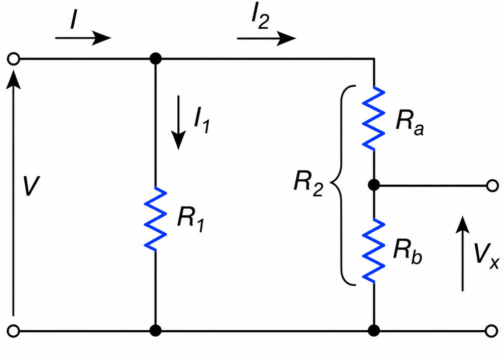
Figure 1-25 Calculating Vx in Resistive Circuit
The expression in (a) is the voltage-divider concept; the expressions in (b) are current-divider concepts.
Solution
The currents through the various resistors are identified as shown in Figure 1-25.
a. Applying Ohm’s law, we obtain
$$V_x = I_2 R_b = \frac{R_b V}{R_a + R_b} = \frac{V}{R_2}R_b$$
b. Again from Ohm’s law, we get the following relationships:
(I)
$$V = I(R_1 \parallel R_2) = I\frac{R_1 R_2}{R_1 + R_2}$$
Also,
(II)
$$V=I_{1}R_{1}$$
and
(III)
$$V=I_{2}R_{2}$$
From (I), (II), and (III), we obtain
$$I_1 = I\frac{R_2}{R_1 + R_2}$$
And
$$I_2 = I\frac{R_1}{R_1 + R_2}$$
Kirchhoff’s Voltage Law
According to Kirchhoff’s voltage law (KVL), the algebraic sum of the electric voltages along a closed loop is equal to zero. That is,
$$\sum V_{\text{Loop}} = 0 \tag{1.69}$$
In applying KVL, the following procedure is recommended:
- Draw or assign loop currents (a loop current is a current that flows in a closed path) in whatever direction is preferable. That is, the clockwise (CW) or counterclockwise (CCW) current direction is arbitrary.
- Assign positive (+) and negative (−) signs to the passive elements. The terminals where the current is entering should be marked positive, and the terminals where the current is leaving, negative. In other words, the terminal of the passive element where the current emerges is at a relatively lower potential than the terminal where the current enters. A good analogy is that current, like free-running water, flows from a higher elevation (potential) to a lower one.
- Identify the relative polarity of the sources (active elements). This is normally given. An arrow, placed between the terminals of a voltage source, indicates the direction of rising potential, and the tip of the arrow points toward the terminal of positive polarity.
- Starting at any convenient point, proceed along a loop summing up all the voltages encountered. According to KVL, these voltages must be equal to zero. That is, $\sum V_{\text{Loop}} = 0$
- It is absolutely necessary to sum up the voltages along a closed loop even if there is no physical connection for the current to flow through. This condition is encountered in some equivalent circuits of electronic devices.
- In proceeding along a loop, one does not have to follow the same direction as the loop current.
- The sign of each voltage term in a KVL equation depends on the polarity of the element first seen as one proceeds along the loop. In going from the positive to the negative terminal of an element, the voltage across this element may be taken as negative. In contrast, in going from a negative to a positive terminal of an element, the voltage across this element must be taken as positive. However, the opposite sign convention could be selected.
- When the correct solution of the loop equations yields a negative current, this means only that the assumed current direction is wrong. The problem does not have to be redone.
Getting out of bed in the morning, doing the day’s work, then returning to the same bed in the evening does not change a person’s potential energy, thus KVL is satisfied.
Similarly, a pump’s power requirement to recirculate water from say a 100 m underground reservoir to surface and vice versa is, because of KVL, almost negligible. (Electric potential is analogous to water elevation—hydrostatic head—in hydraulics).
Example 1-8
Write the loop equation for the circuit shown in Figure 1-27(a).
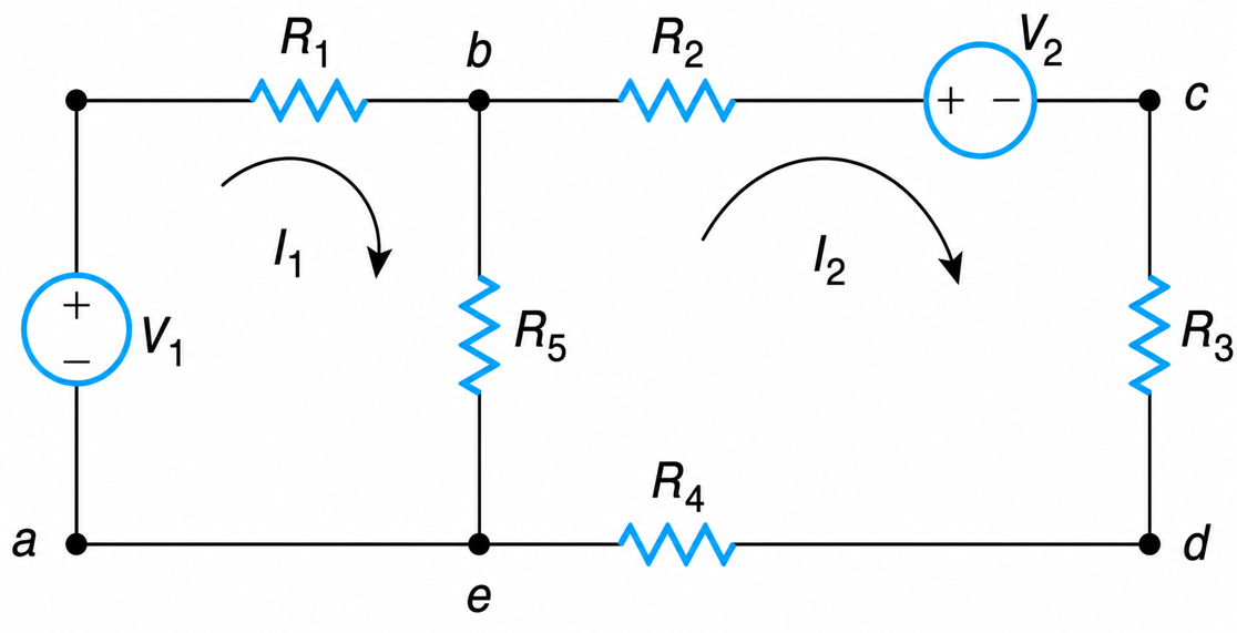
Figure 1-27 Loop Equations for Electric Circuit
Solution
Currents I1 and I2 flow in loop 1 and loop 2, respectively. Clockwise direction is arbitrarily chosen for all loop currents. The sign, or the relative polarity across each element, is designated as shown.
Loop 1
$$(a-b-e-a)$$
Applying KVL, we obtain
$$V_1 - I_1R_1 - I_1R_5 + I_2R_5 = 0$$
The voltage across R5 is due to the currents I1 and I2. These currents pass in opposite directions through the same resistance and will result in voltage drops of opposite polarity.
Loop 2
$$(b-c-d-e-b)$$
Applying KVL again, we get
$$I_2R_2 + V_2 + I_2R_3 + I_2R_4 + I_2R_5 - I_1R_5 = 0$$
Kirchhoff’s Current Law
According to Kirchhoff’s current law (KCL), the algebraic sum of the currents into a junction is equal to zero. That is,
$$\sum I_{\text{junction}} = 0 \tag{1.70}$$
In other words, the incoming currents to a junction must be equal to the outgoing currents.
In applying KCL, the following procedure is recommended:
- Identify and designate all the points on the circuit that are at different potentials. These points are referred to as the nodes of the circuit. For this reason, Equation (1.70) is often referred to as the nodal equation.
- Select a reference node—that is, a point of zero potential.
- Apply KCL to each node. It is very important to note that the node under consideration has the highest potential in the circuit, and thus the currents leave the node unless they are injected into it by a current source.
- The currents that leave the node must be designated with a sign opposite to those approaching the node.
Example 1-9
Determine a general expression for the voltage at node B in Figure 1-28.
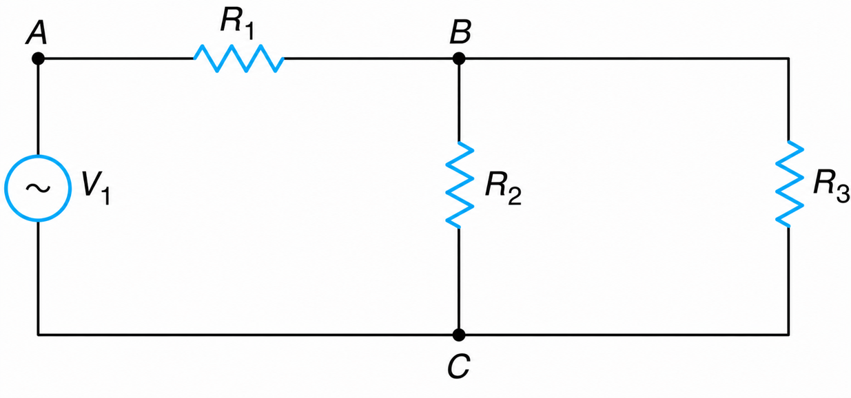
Figure 1-28 Node Equations for Electric Circuit
Solution Node A
There are three nodes—A, B, and C. Select node C as reference. Applying KCL in node B, we obtain
$$\frac{V_B}{R_2} + \frac{V_B - V_A}{R_1} + \frac{V_B}{R_3} = 0$$
$$V_A = V_1$$
From above,
$$V_B\left(\frac{1}{R_1} + \frac{1}{R_2} + \frac{1}{R_3}\right) = \frac{V_1}{R_1}$$
Or
$$V_B = \frac{V_1}{R_1}\left(\frac{R_1R_2R_3}{R_2R_3 + R_1R_3 + R_1R_2}\right)$$
Ohm’s and Kirchhoff’s laws are the outstanding principles of electrical engineering. The design of all circuits must always satisfy these laws.
The high starting current in three-phase induction machines, the high short-circuit currents of ac machines, the sparking that accompanies the interruption of current through various coils, and the occasional fires that result from electric circuits are all caused by reactions of nature that attempt to satisfy these basic principles.