Basic Electrical Elements
The basic building blocks of Electrical Engineering are:
- Resistance,
- Inductance, and
- Capacitance
An understanding of their characteristics will simplify many concepts and applications in power distribution, magnetism, and electronics. Their analogy to mechanical systems will drive the point home and will also facilitate the understanding of some theoretical and practical aspects of heat transfer and hydraulics.
Resistance
1 Physical Significance
In a dc circuit, the opposition to the flow of current is called resistance. It is equivalent to the friction in a moving body. The higher a material’s temperature, the higher the agitation and collision of its atoms and thus the higher its opposition (resistance) to the passage of electrons (current).
2 Symbols and Designation
The symbol of a fixed and variable resistor is shown in Figure 1-7(a).
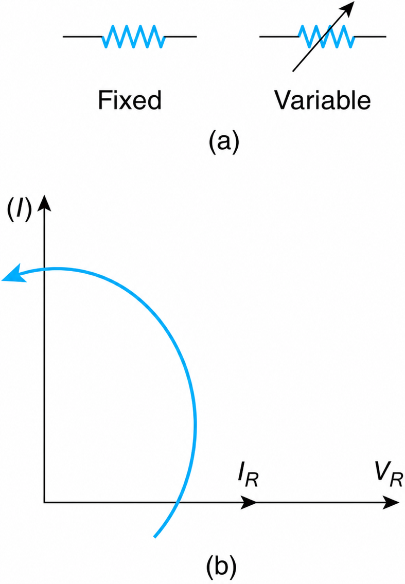
Figure 1-7 Resistors. (a) Fixed and variable resistor. (b) Voltage–current phasors.
3 Unit
The resistance is measured in ohms $\Omega$.
$$10^{-3}\,\Omega = 1\,\text{m}\Omega$$
$$10^{3}\,\Omega = 1\,\text{k}\Omega$$
The minimum resistance in a 240/120 V, 100 A home is $3\Omega$, while that of a human body is in the range of hundreds to thousands of ohms.
In all power distribution drawings, however, the ohmic values of resistances (motors, transformers, cables, etc.) are replaced by their equivalent “per unit values.” The latter reveal by inspection many characteristics of the device under consideration.
4 Design
The resistance (R) of a conductor whose cross-sectional area is constant is given by
$$R = \rho \frac{\ell}{A} \tag{1.20}$$
where p is the resistivity of the conductor’s material expressed in $\Omega\times m$, $l$ is its length expressed in m, and A is the conductor’s cross-sectional area perpendicular to the flow of the current, expressed in m2.
By inspecting Equation (1.20), it is clear that conductors of a larger cross-sectional area have lower resistance than conductors of a smaller cross-sectional area. Thus, in order to minimize the resistance of a winding (wire forming one or more loops, often referred to as a coil or inductor), a wire of as large a cross-sectional area as can be physically accommodated must be used.
When caught outdoors during a thunderstorm, running to the nearest depression in the ground increases the body’s resistance and thus lessens the destructive effects of any lightning.
The resistivity of any material depends on its atomic structure and on its temperature. At 20 oC, the resistivity of aluminum is 1.64 times greater than that of copper.
5 Effects of Temperature
The resistance of a wire as a function of temperature is given by
$$R = R_0 \left[1 + \alpha_{20}(T - 20)\right] \tag{1.21}$$
where $R_{o}$ is the resistance of the wire at 20 oC, R is its resistance at T oC , and $\alpha _{20}$ is the temperature coefficient at 20 oC. The temperature coefficient for copper is $0.00393/^\circ\text{C}$; for tungsten, it is $0.0045/^\circ\text{C}$. Then from Equation (1.21), the temperatures at which copper and tungsten become superconductive (i.e., have resistance equal to zero) are -234.45 oC and -202.2 oC, respectively. Recently, a new class of ceramic material has been developed that becomes superconductive at much higher temperatures.
Did You Know?
The phenomenon of superconductivity was first observed in 1911 by a Dutch physicist Heike Kamerlingh Onnes in 1911. He was the first scientist to liquefy helium in 1908, which set the stage for his best-known work, the discovery of superconductivity three years later. He noted that the resistance of a frozen mercury rod abruptly dropped to zero when cooled to the boiling point of helium (4.2 Kelvin).
6 Voltage across a Resistor
From Ohm’s law, the voltage (V) across a resistor is given by
$$V = IR \tag{1.22}$$
where I and R are, respectively, the current and the circuit’s resistance.
7 Phasor
The voltage and the current in a resistor, as can be concluded from Equation (1.22), are in phase. They are sketched in Figure 1-7(b).
8 Power
The power (P) consumed by a resistor is
$$P = VI = \frac{V^2}{R} = I^2 R \tag{1.23}$$
The power, or the rate of heat loss, in a winding depends on its resistance, which in turn depends on its operating temperature. When speaking of the losses of an apparatus, the temperature to which these losses correspond must be specified.
9 Energy
By definition, the energy (W) is related to the power (P) by
$$W = P(\text{time}) = I^2 R (\text{time})$$
It is measured in kWh.
10 Combination of Resistors
Given the resistors R1, R2, and Rn, their equivalent (Re) series and parallel combinations are as follows.
a. Series combination (Figure 1-8)
$$R_e = R_1 + R_2 + \cdots + R_3 \tag{1.24}$$
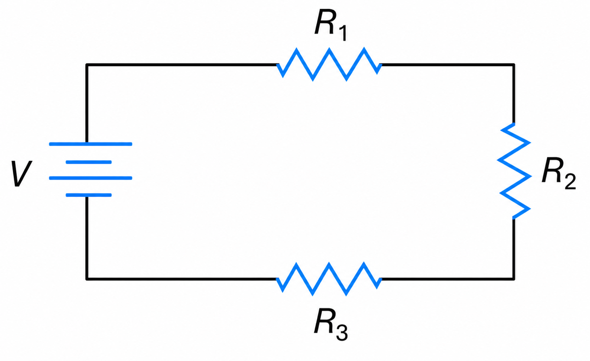
Figure 1-8 Resistors in series.
b. Parallel combination (Figure 1-9)
$$\frac{1}{R_e} = \frac{1}{R_1} + \frac{1}{R_2} + \cdots + \frac{1}{R_n} \tag{1.25}$$
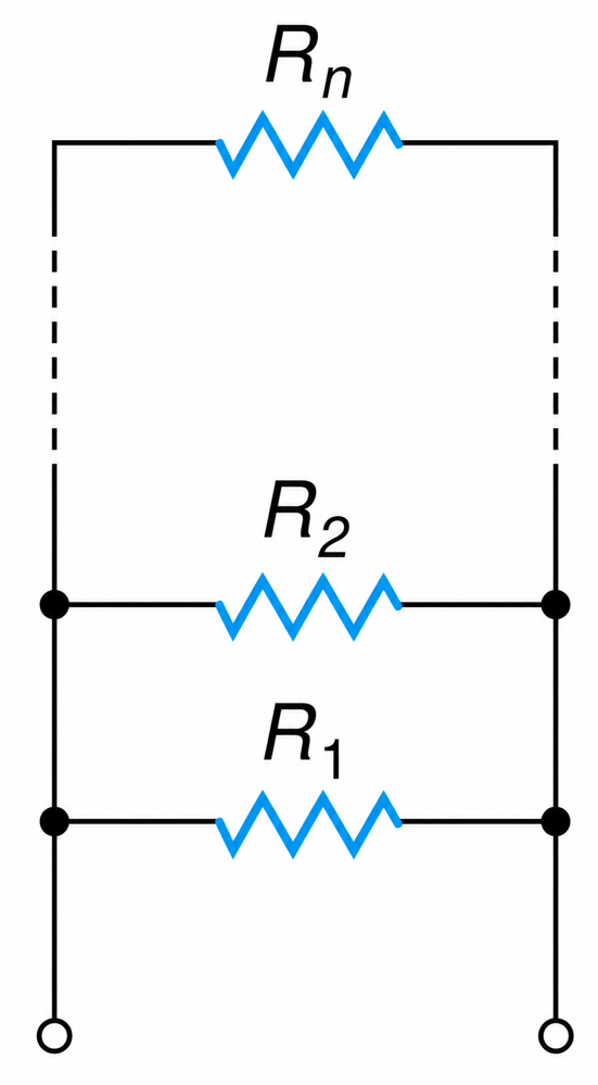
Figure 1-9 Resistors in parallel.
The equivalent resistance of two parallel resistors R1 and R2 is
$$R_e = \frac{R_1 R_2}{R_1 + R_2} \tag{1.26}$$
Example 1-3
a. Given three copper resistors, each of $10\Omega$, find their equivalent resistance when they are connected in parallel.
b. Find the percentage change in the equivalent resistance when their temperature increases by .
Solution
a.
$$\frac{1}{R_e} = \frac{1}{R_1} + \frac{1}{R_1} + \frac{1}{R_1} = \frac{1}{10} + \frac{1}{10} + \frac{1}{10}$$
And
b.
$$R_e = 3.33\,\Omega$$
and the percentage change is:
$$R_e = 3.33(1 + 0.00393)(20)$$
$$R_e = 3.60\,\Omega$$
$$= \frac{3.60 - 3.33}{3.33}(100) = \underline{7.86\%}$$
Self-Inductance
The inductance is associated with a magnetic field, and since the latter is due to flow of current, it can be said that conductors that carry current always have an inductance or simply a self-inductance.
When the flux lines of one coil link an adjacent coil and vice versa, then there is a mutual coupling between the coils and/or a mutual inductance.
1 Physical Significance
The inductance (L) of a coil or of a winding is analogous to the mass (M) of a moving object or to the polar moment of inertia (J) of a rotating body.
The electrical momentum (LI) corresponds to the mechanical momentum (MU). Mathematically,
$$LI\,\Xi\,MU \tag{1.27}$$
and
$$LI\,\Xi\,j\omega \tag{1.28}$$
where ω is the angular rotation of the rotating body.
The flow of current through a circuit of high inductance cannot be interrupted instantaneously, just as a large moving object cannot be stopped. Interrupting the flow of current in a highly inductive circuit is as destructive as attempting to stop a moving truck.
2 Unit
The inductance is measured in the Henry (H).
$$10^{-3}\,\text{H} = 1\,\text{mH}$$
$$10^{-6}\,\text{H} = 1\,\mu\text{H}$$
The inductance of a transformer could be several mH, while that of a relay could be in the range of Henries.
3 Design
The inductance of a coil depends on its physical characteristics (K1), on the permeability of its material $\mu $, and on the number of turns squared. Mathematically,
$$L = K_1 \mu N^2 \tag{1.29}$$
For constant permeability,
$$L = K N^2 \tag{1.30}$$
where K is a constant.
Since almost all loads have winding turns (motors, transformers, etc.), it can be said that the loads in industrial plants are inductive.
4 Voltage
The voltage ($v$) across an inductor is given by
$$\upsilon = L \frac{di}{dt} \tag{1.31}$$
or
$$\upsilon = N \frac{d\phi}{dt} \tag{1.32}$$
where i is the current as a function of time, N is the number of winding turns, and $\phi $ is the magnetic flux. When the slope or the time rate of change of the current or that of the flux are high, the voltage across the inductor will be high.
5 Impedance
The impedance (ZL) or the opposition of an ideal inductor to the flow of current is
$$Z_L = j 2\pi f L \tag{1.33}$$
$$Z_L = j\omega L \tag{1.34}$$
$$Z_L = jX \tag{1.35}$$
where f and ω are, respectively, the supply voltage’s natural frequency of oscillation and the angular frequency of oscillation. X is called the reactance of the coil and is measured in ohms. The impedance is a phasor, while the reactance is a scalar quantity.
The impedance of an inductor can also be represented by the Laplace notation as follows
$$Z_L = sL \tag{1.36}$$
where s is the Laplace operator.
6 Phasor Diagram
From Ohm’s law, the current (I) in an inductor is given by
$$I_L = \frac{V_L}{Z} \tag{1.37}$$
From above,
$$I_L = \frac{V_L}{jX} \tag{1.38}$$
$$= \frac{V_L}{X} \angle -90^\circ \tag{1.39}$$
That is, the current is lagging the voltage by 90 degrees. This is indicated in Figure 1-10(b).
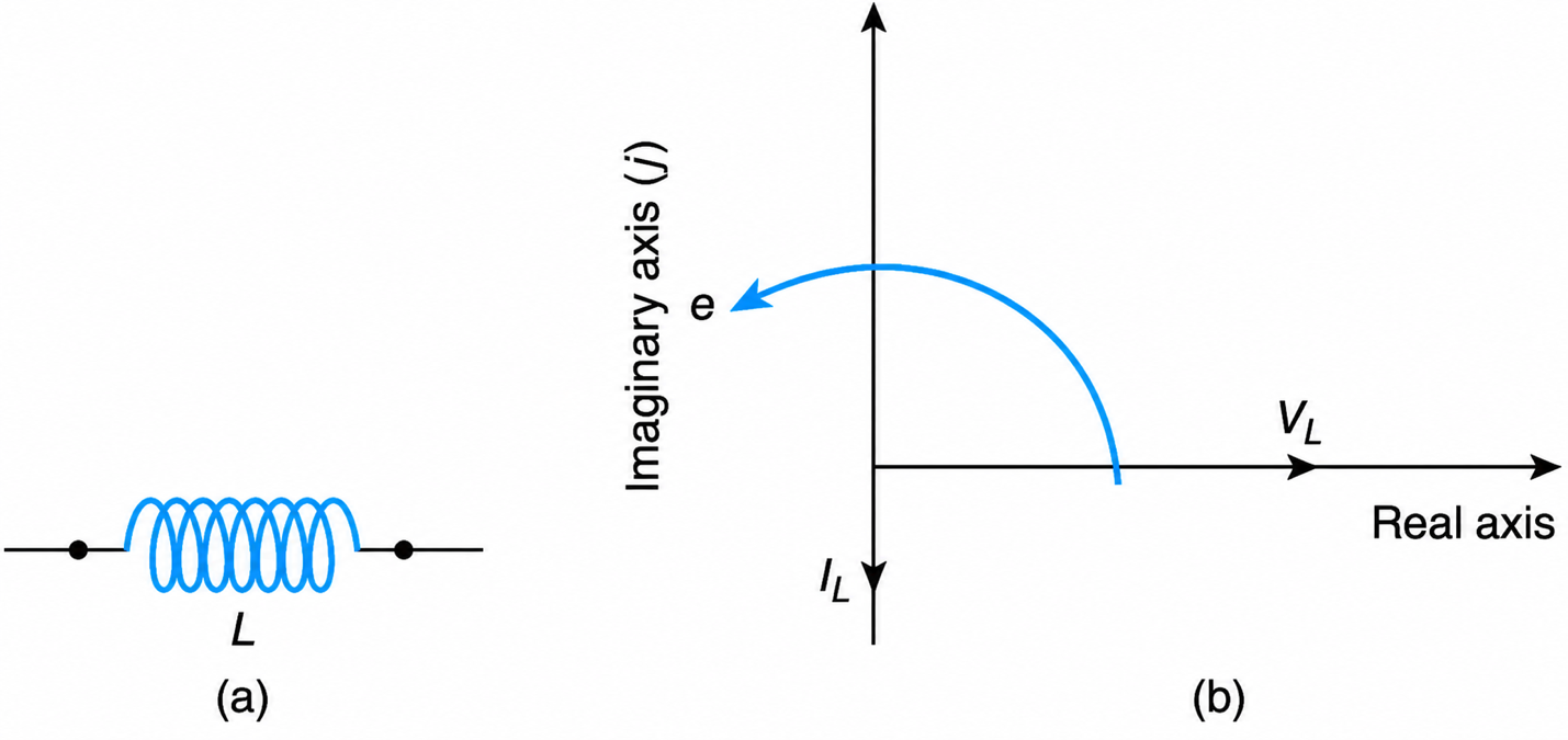
Figure 1-10 (a) Inductor. (b) Voltage-current phasor.
Physical Justification
An inductor is a characteristic of a magnetic field that is due to current flow. Current flow follows, as per Ohm’s law, the application of voltage. That is, the voltage across an inductor proceeds (leads) the current or the current through an inductor lags the voltage.
7 Power
The average power (P) is given by
$$P = VI \cos\theta \tag{1.40}$$
Since the phase angle $\theta $ between the voltage and the current is 90 degrees, the inductors consume no power.
8 Energy Stored
The expression for the energy (W) stored in a coil is derived as follows:
$$dW = P\,dt \tag{1.41}$$
$$W = \int \upsilon i \, dt \tag{1.41a}$$
$$= \int L \frac{di}{dt}\, i \, dt \tag{1.41b}$$
$$= \int_{0}^{I} L\, i \, di \tag{1.41c}$$
$$= \frac{1}{2} L I^2 \;\text{watt-seconds} \tag{1.41d}$$
The energy in a coil or that in any magnetic field contrary to that of capacitors is released on current interruption. This property of the inductive loads may damage electronic circuits and poses a safety hazard for personnel. It is for that reason that in electronic circuits a discharge resistor should be connected in parallel with the inductors.
For example, pulling the cable of an operating toaster from its power supply receptacle, causes a spark. This could be attributed to the momentary discharge of the energy stored in the inductance of the circuit across the receptacle.
9 Starting Current
When a coil or a motor at rest is connected to a voltage supply, its starting currents are zero. In general, the inductor is open circuit at t=0.
For a coil,
$$Z_L = j\omega L \tag{1.42a}$$
$$Z_L = sL \;\text{ohms} \tag{1.42b}$$
At $t\to 0$, $s\to \infty$ and the coil’s impedance is infinite.
To prevent electrical disturbances, such as lightning strokes, from reaching a sensitive electronic device, a coil of high inductance is used upstream of it. (In Europe, an inductance is inserted in series with the supply power lines, while in some parts of North America, a transformer of turns ratio equal to unity is used.)
Furthermore, medical devices that are used to apply a high voltage to a patient with a defibrillating heart usually include an inductance so that when they are switched ON, the current is zero and desired levels are reached with further adjustments.
10 Time Constant
The current in every dc or ac circuit has a dc component that is of the form
$$I_t = A_0 e^{-at} \tag{1.43}$$
where Ao and a are the circuit’s constants. 1/a is termed the circuit’s time constant (tc). That is,
$$tc = \frac{1}{a} \tag{1.44}$$
This definition of tc makes the exponent equal to minus 1. In an R-L circuit,
$$tc = \frac{L}{R} \tag{1.45}$$
There are other designations that describe the decay of exponential functions.
Chemists and physicists speak of the half-life expectancy of the variable under consideration, while often in applied science, the time constant is defined as the value of t, at which the function’s value is 0.37 of its original value.
In contrast to these alternatives, use the definition given previously, because in practice, it is important to know how long it will take for the exponential decaying function to become zero. The corresponding time interval is about four time constants (Figure 1-11).
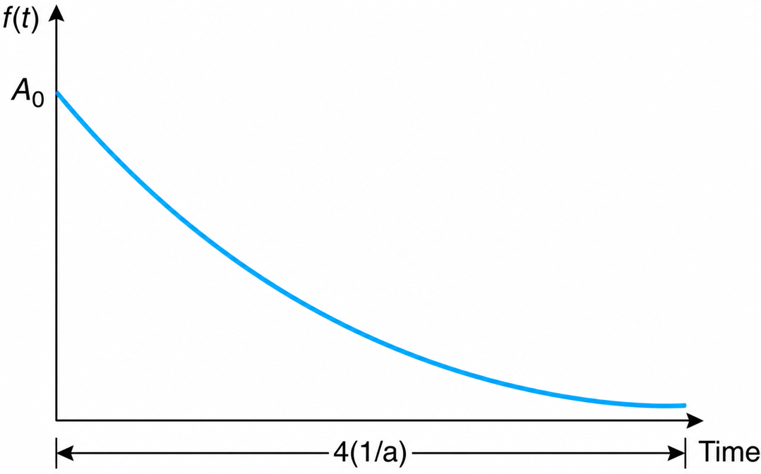
Figure 1-11 Exponential decaying function
When a standard ac motor is switched on to its nominal voltage supply, its starting current is about six times its rated value and its duration is four time constants. That is, its rate of heat loss I2R is 36 times its rated value during the starting period. The time constant of the human eye is about 1 m-sec.
When a utility transfers a city’s distribution system from one generating station to the other, the corresponding circuit breakers open and close in less than 4 m-sec, and thus a human’s eyes do not notice the change in illumination levels.
Similarly, when a room’s temperature should be decreased or increased to a desired value through the air supply, it will take four time constants to reach the desired temperature. Since the inductance is equivalent to mass, the system’s time constant is equal to
$$\frac{\text{room's equivalent air volume}}{\text{rate of supply air volume}}$$
A better method is to develop and solve the corresponding differential equation.
11 Resonance Condition
Refer to Figure 1-12. At resonance, the circuit’s current is maximum. This implies that the impedance (Z) is minimum.
$$Z = R + j\omega L + \frac{1}{j\omega C} \tag{1.46}$$
where $\frac{1}{j\omega C}$ is the impedance of the capacitor.
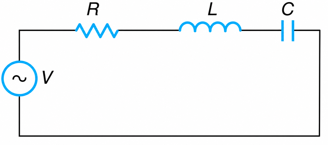
Figure 1-12 An R-L-C circuit.
For the current to be maximum,
$$j\omega L + \frac{1}{j\omega C} = 0 \tag{1.47}$$
From which,
$$\omega^2 = \frac{1}{LC} \tag{1.48}$$
or
$$f_0 = \frac{1}{2\pi\sqrt{LC}} \tag{1.49}$$
where fo designates the natural frequency of oscillation.
In general, resonance condition is a condition of maximum current or voltage or love or hate or patriotism, and so on. Every circuit or building or individual has its own unique resonant frequency or sensitivity.
12 Combination of Inductors
The series and parallel equivalent of individual inductors is, as shown in Figure 1-13, identical to those of resistors.
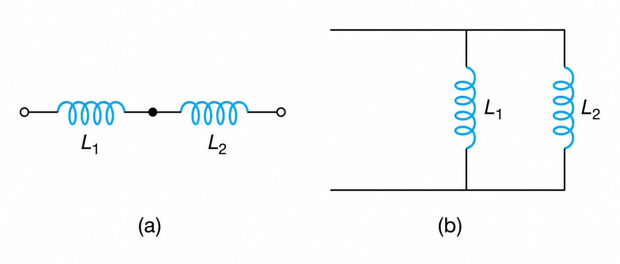
Figure 1-13 Ideal Inductors. (a) Series connection. (b) Parallel connection.
Example 1-4
Refer to Figure 1-14.
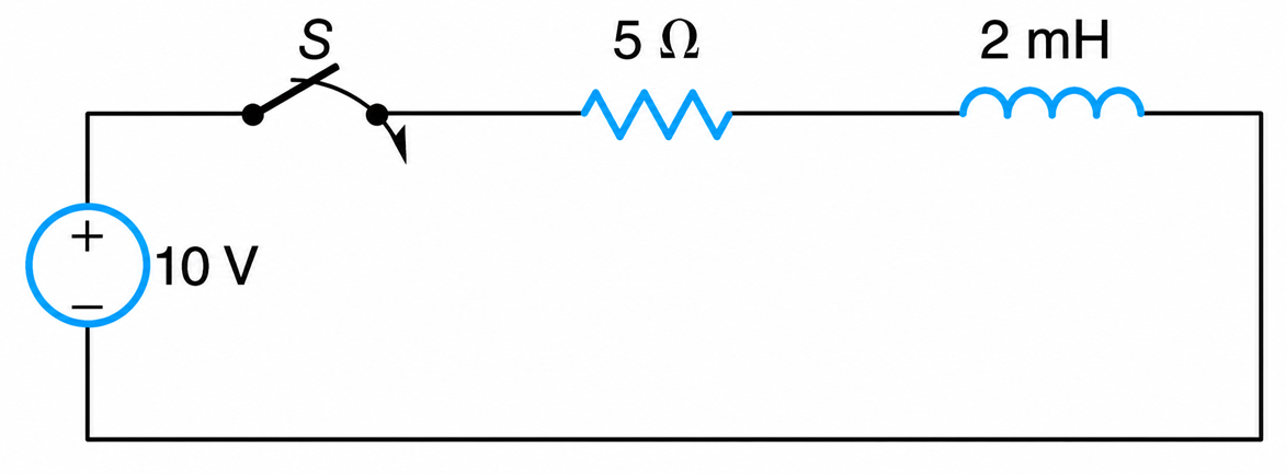
Figure 1-14 RL Series Circuit
a. When the switch S is closed for a long time, determine the energy stored in the inductance.
b. When the switch becomes open, find how long it will take for the energy to be dissipated.
Solution
a.
$$I = \frac{V}{R} = \frac{10}{5} = 2\,\text{A}$$
$$W = \frac{1}{2} L I^2 = \frac{1}{2}(2)^2(2 \times 10^{-3}) = 4\,\text{m watt-seconds}$$
b.
The energy will take about four time constants to decay to zero.
$$4\frac{L}{R} = 4\frac{L}{\infty} = 0.0\,\text{second}$$
(When the switch is open, its resistance is infinite).
Capacitance
1 What Is a Capacitance?
Capacitance is associated with the force between two objects, one of which has free positive charges and the other free negative charges. This force is directed from the positive to the negative charges. When moving along a room, the capacitance changes with respect to the encountered objects because the object’s free electron charges are different in polarity (positive or negative) with respect to the moving individual.
As such, there is always a capacitance between an overhead transmission line and the ground, between an individual and a radio, between the room’s lighting fixtures and a student in the classroom. In other words, there is almost always a capacitance between two objects. This physical phenomenon is used in measurements and analysis of transmission line problems, in the noncontact voltage detecting “stick” of the electricians, etc.
Figure 1-15(a) shows two capacitor plates that are connected to a dc voltage supply of V volts. The upper plate is positively charged, and the lower plate negatively charged.
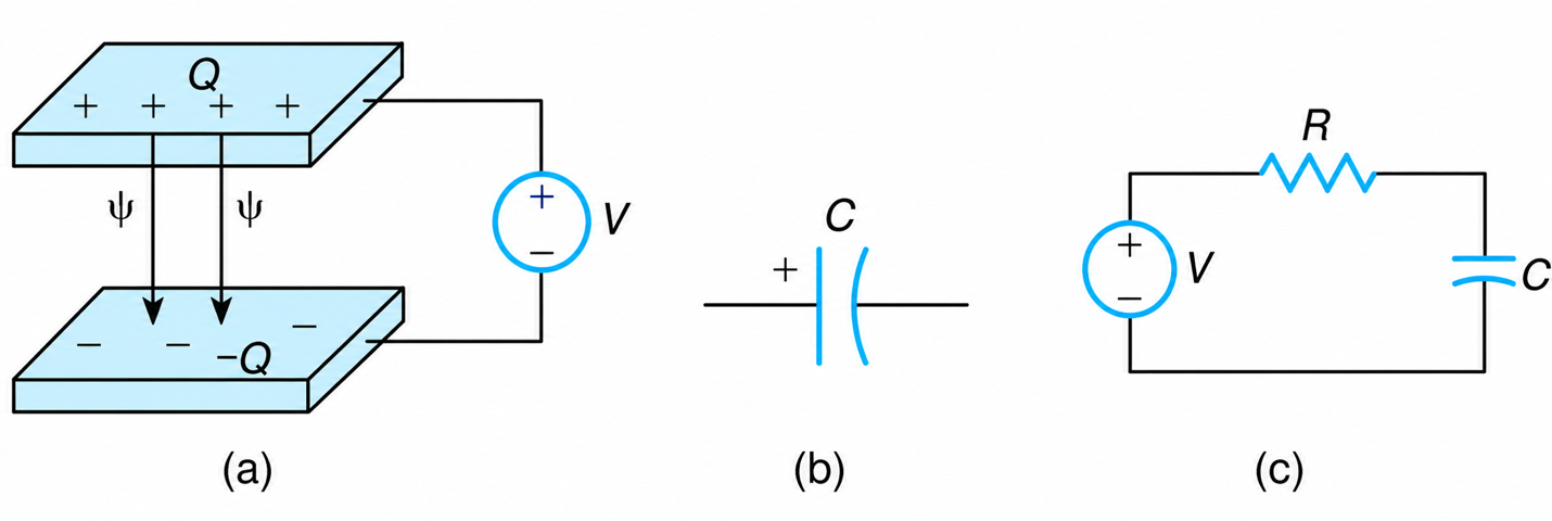
Figure 1-15 Capacitor. (a) Charged capacitor plates. (b) Ideal capacitor. (c) Capacitive circuit.
The vector $\psi $ between the plates represents the electric flux or the electric lines of force. The electric flux emerges from the positively charged plate and terminates in the negatively charged plate. According to Gauss’s law, the electric flux is equal to the number of free charges in one plate.
2 Unit
The unit of a capacitor is the Farad (F)
$$10^{-3}\,\text{F} = 1\,\text{mF}$$
$$10^{-6}\,\text{F} = 1\,\mu\text{F}$$
And
$$10^{-12}\,\text{F} = 1\,\mu\mu\text{F}$$
The capacitance between a ceiling’s lighting fixture in a classroom and a student is about $50 \mu \mu F$, while that of industrial capacitors is in the range of mF.
3 Design
In an ideal case, the capacitance of two parallel plates is given by
$$C = \varepsilon \frac{A}{d} \tag{1.50}$$
where
- C is the capacitance of the two plates (F)
- $\varepsilon$ is the permittivity of the material between the capacitor plates (F/m)
- A is the cross-sectional area of one plate (m2)
- d is the perpendicular distance between the plates (m).
The permittivity $(\varepsilon)$ of a material is equal to the permittivity of free space $(\varepsilon _{o})$ times the relative permittivity $(\varepsilon _{r})$ of the material. That is,
$$\varepsilon = \varepsilon_r \varepsilon_0 \tag{1.51}$$
The relative permittivity of paper is about 80 times larger than that of air. In the tuning of some radios, the parallel capacitor plates are moved in relation to each other, and thus their effective area changes, resulting in a new capacitance. The new capacitance, according to the theory of resonant circuits, produces a new resonant frequency, and thus the radio can pick up a new station. A capacitor is sometimes referred to as a condenser.
4 Capacitor-Charge Relationship
The capacitance of the two plates is also given by
$$C = \frac{Q}{v_c} \tag{1.52}$$
where Q is the electric charge of one plate and $v_{c}$ is the voltage between the two plates.
5 Capacitor Voltage
The circuit representation of an ideal capacitor is shown in Figure 1-15(b). The current ic to the capacitor is, by definition, equal to the time rate of change of the electric charge. That is,
$$i_c = \frac{dQ}{dt} \tag{1.53}$$
From Equation (1.52) and (1.53) we get
$$v_c = \frac{1}{C} \int i_c \, dt \tag{1.54}$$
Equation (1.54) is a general expression for the voltage across a capacitor. When the current is constant, the voltage across the capacitor increases linearly with time.
6 Impedance
The impedance (Zc) or the opposition to the current presented by a capacitor is
$$Z_c = \frac{1}{j\omega C}\;\text{ohms} \tag{1.55a}$$
$$Z_c = j \frac{1}{j^2 \omega C} \tag{1.55b}$$
$$Z_c = -j\left(\frac{1}{\omega C}\right) \tag{1.55c}$$
$$Z_c = -jX_c\;\text{ohms} \tag{1.55d}$$
where ω is the angular frequency (rad/s) of the voltage source and Xc is the reactance of the capacitor measured in ohms. The impedance of a capacitor can also be represented in terms of the Laplace operator
$$Z_c = \frac{1}{sC}\;\text{ohms} \tag{1.56}$$
7 Phasor
From Ohm’s law, for a pure capacitor
$$I_c = \frac{V_c}{Z_c} \tag{1.57a}$$
$$= \frac{V_c}{1/j\omega C} \tag{1.57b}$$
$$= j\omega C V \tag{1.57c}$$
$$= \omega C V \angle 90^\circ \tag{1.57d}$$
That is, the current in a capacitor leads the voltage by 90 degrees (see Figure 1-16).
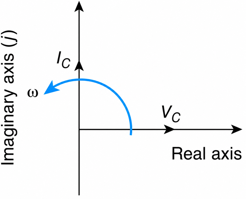
Figure 1-16 Capacitor’s voltage-current phasors.
Physical Justification
The voltage across a capacitor is due to electronic charges on its plates. These charges were carried to the plates through some kind of current flow. That is, the current to a capacitor precedes the development of voltage across it or the voltage lags behind the current.
8 Power
The average power consumed by a capacitor is
$$P = VI \cos\theta \tag{1.58}$$
where $\theta$ is the phase angle between the voltage and the current. This phase angle is 90 degrees and thus,
$$P=0$$
That is, an ideal capacitor does not consume any power.
9 Energy
The incremental energy (dW) gained by a capacitor in an infinitesimal amount of time dt is
$$dW = v_c i_c \, dt \tag{1.59}$$
From the above and Equation (1.53), we obtain
$$dW = v_c \, dQ \tag{1.60}$$
Substituting for dQ, its equivalent from Equation (1.52), we get
$$dW = C v_c \, dv_c \tag{1.61}$$
Taking integrals and assuming that the voltage changes from zero up to V volts, we obtain the energy stored within the electric field of a capacitor:
$$W = C \int_{0}^{v} v_c \, dv_c = \frac{1}{2} C V^2 \tag{1.62}$$
where W is the energy stored in the electric field and V is the voltage across the capacitor.
When the current in a capacitor is interrupted, the capacitor remains charged. Depending on the magnitude of its voltage, it may be hazardous to personnel. When the switch is closed, the supply voltage may aid the capacitor voltage. As a result, the voltage across the switch will be, instantaneously, twice that of the supply voltage. This again may be hazardous to personnel and may also carbonize the contacts of the switch, causing it to malfunction.
Carbonization is probably the most common cause of failure of equipment that is called upon to start and stop frequently: air conditioners, clothes washers, and the like. An international company that operates public clothes washing machines reported an annual failure rate of about 12%. The major cause, as determined by consultants, was the carbonization of the timer’s contact that resulted from the circuit capacitors.
To eliminate these problems the capacitors should be connected in parallel to properly sized resistors so that the stored energy may be safely dissipated as heat. For these reasons, the electrical code requires that a capacitor in a power distribution network that is rated at less than 750 V should be equipped with a parallel-connected resistor so that the stored energy may be dissipated in less than 60 seconds.
10 Starting Current
Equation (1.56) is important in evaluating the effect of a capacitor on a distribution system. Theoretically, s approaches infinity at t=0. That is, the impedance of a capacitor is zero, and thus from Ohm’s law the current is infinite.
In practice, ideal capacitors do not exist. Manufacturers report that at t=0 (starting current) could be up to 300 times rated. In order to eliminate this adverse effect of the capacitors, their power supply cable should be rolled up in two to three turns so that an inductance is introduced into the circuit.
11 Time Constant
The time constant of an RC circuit is
$$tc = CR \;\text{seconds} \tag{1.63}$$
12 Displacement Current
In an attempt to explain the existence of magnet fields in empty space, James Maxwell postulated that there must be a capacitor current, which he called displacement current, Id. This current is not like the conduction current (rate of electrons’ flow), but it is given by the rate of change of electric flux lines. That is,
$$I_d = \frac{d}{dt}(\Psi) \tag{1.64}$$
This current does not flow through the air between the capacitor plates. Maxwell justified it by reasoning that the time rate of change of the electric flux lines stretch or modify the atoms’ electron configuration—a form of current—and thus there must also be a changing magnetic field within the air space.
13 Resonance Condition
The capacitor is used to adjust the resonant frequency (fo) of an electronic circuit. The resonant frequency given by Equation (1.49) is rewritten here as
$$f_o = \frac{1}{2\pi\sqrt{LC}} \tag{1.65}$$
where L and C are, respectively, the circuit’s inductance and capacitance. In selecting a radio station or a TV channel, it is usually done by adjusting the capacitance between two spherical disks, one of which moves with respect to the other.
14 Combination of Capacitors
The equivalent of a series-connected capacitor is similar to that of parallel-connected resistors. Similarly, parallel-connected capacitors are equivalent to series-connected resistors.
15 Types of Capacitors
There are the following three types of capacitors: electrostatic, electrolytic and supercapacitors.
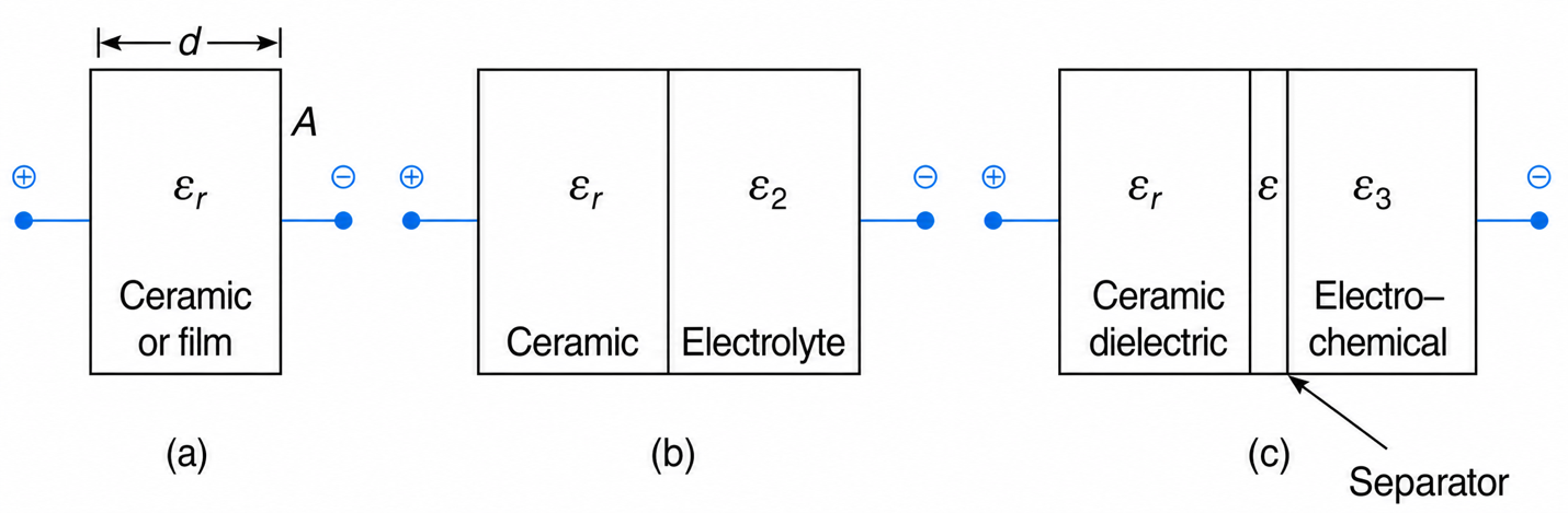
Figure 1-17 Capacitors. (a) Electrostatic (dry separator). (b) Electrolytic (moist separator). (c) Supercapacitor organic electrolyte.
Electrostatic
The electrostatic or classical capacitors have a capacitance in the range of $\mu \mu F$ to several $\mu F$. Their capacitance, depends, as previously described, on the permittivity of the insulating material between the capacitor plates, the separation distance between the plates, and the area of one of the plates. It is used in radio and in tuning circuits. The energy storage capability of electrostatic capacitors is very small.
Electrolytic
Electrolytic capacitors have a capacitance that is much larger than that of the classical capacitors. As the name implies, there is an electrolytic chemical between the capacitor plates that are marked positive (+) and negative (−). When the applied dc voltage has opposite polarity to that of the plates, the capacitor will be instantly damaged.
The derivation of the capacitance between the plates is derived by using the Laplace equation, which describes the electric fields. Alternatively, the capacitance of an electrolytic capacitor is equal to the parallel combination of two capacitors, each of whose capacitance is given by Equation (1-50), modified according to the dimensions and permittivity of each layer.
Supercapacitor
The Supercapacitor has two layers of carbon-based organic electrolytes that are separated by a nonconducting thin plate whose thickness is in the range of nanometers. The supercapacitor is the latest improvement in storing energy in an electric field, and because its capacitance could be up to several thousand Faradays, in some applications, it can replace the standard batteries.
Figure 1-18 shows the development of a supercapacitor in China. Table 1-1 compares some characteristics of the supercapacitors with those of standard Li-ion batteries.
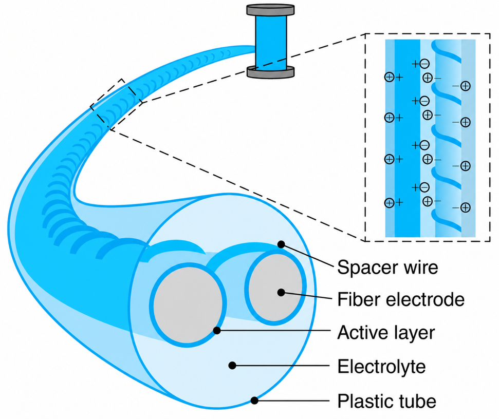
Figure 1-18 Supercapacitors.
Table 1-1 Relative Characteristics of Li-ion Batteries and Supercapacitors
|
No. |
Characteristics |
Battery |
Supercapacitors |
|
1 |
Voltage range |
Low |
Lower |
|
2 |
Energy stored per unit volume |
Low |
Lower |
|
3 |
Charging time |
High |
Higher |
|
4 |
Discharging time |
Short |
Shorter |
Mathematical Considerations
A supercapacitor can be represented by the resistance R1 (Figure 1-19) in series with a capacitor that in turn is connected in parallel with the resistor R2.
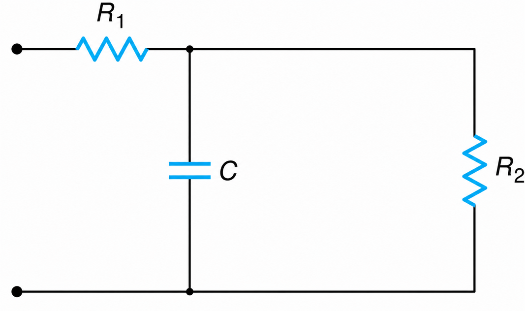
Figure 1-19 Approximate equivalent circuit of a supercapacitor.
The input impedance Z to the circuit is //
$$Z = R_1 + R_2 \parallel \frac{1}{j\omega C} = R_1 + \frac{R_2}{1 + j\omega C R_2}$$
$$Z = R_1 + \frac{R_2(1 - j\omega C R_2)}{1 + (\omega C R_2)^2}$$
$$Z = R_1 + \frac{R_2}{1 + (\omega C R_2)^2} - j\frac{\omega C R_2^2}{1 + (\omega C R_2)^2}$$
For $(\omega C R_2)^2 > 1$, we obtain
$$Z = R_1 + \frac{1}{R_2(\omega C)^2} - \frac{j}{\omega C}$$
The effective circuit resistance Re and capacitance Ce are, respectively,
$$R_e = R_1 + \frac{1}{(\omega C)^2 R_2}$$
$$C_{ef} = C$$
The circuit’s time constant (tc) on capacitor charging is
$$(tc)_{ch} = C\left(R_1 + \frac{1}{(\omega C)^2 R_2}\right)$$
The charging time is several seconds long.
On opening the circuit, the capacitor C is discharged through R2 and the discharge time constant is
$$(tc)_{dis} = C R_2$$
When the capacitor is switched OFF, the discharge time is very small, and therefore the electrodes may overheat and produce sparks.
Did You Know? Scientists Build Incredible Supercapacitor Using Ink from Ordinary Pens
Researchers from Peking University in Beijing, China built the device by coating two long, thin, carbon fibers with the ink, then wrapping them in a flexible plastic casing, filled with electrolyte. The pen ink was used in the supercapacitor after the same team discovered that it contains carbon nanoparticles—perfect for storing charge. When applied to the carbon electrode, it provides an enormous surface area for holding charge: per gram of ink.
Example 1-5
a. The voltage between the plates of a $2\mu\mu F$ capacitor is 10 V. Estimate the number of electric flux lines between the plates.
b. An electronic circuit’s capacitor and its discharge resistor are, respectively, 15 mF and $2k\Omega$. Determine the time it will take for the capacitor to be discharged.
Solution
a.
$$Q = CV$$
$$Q = 2 \times 10^{-12}(10) = 20 \times 10^{-12}\ \text{Coulombs}$$
$$1\ \text{Coulomb} = 6.25 \times 10^{18}\ \text{electrons}$$
Thus,
$$Q = 20 \times 10^{-12}(6.25 \times 10^{18}) = 12.5 \times 10^{7}\ \text{electrons (flux lines)}$$
b.
$$\text{The discharge time} = 4RC$$
$$= 4(2 \times 10^{3})(15 \times 10^{-3}) = \underline{120\ \text{seconds}}$$