Torque and Power Relationships in Induction Motor
Torque and power relationships will be derived by using the equivalent circuit shown in Figure 3-12(d). In deriving the general expression for the torque of an induction motor, the effects of the magnetizing impedance will be neglected. Because this magnetizing impedance is relatively large, its effect on torque developed by the motor at full load is negligible.
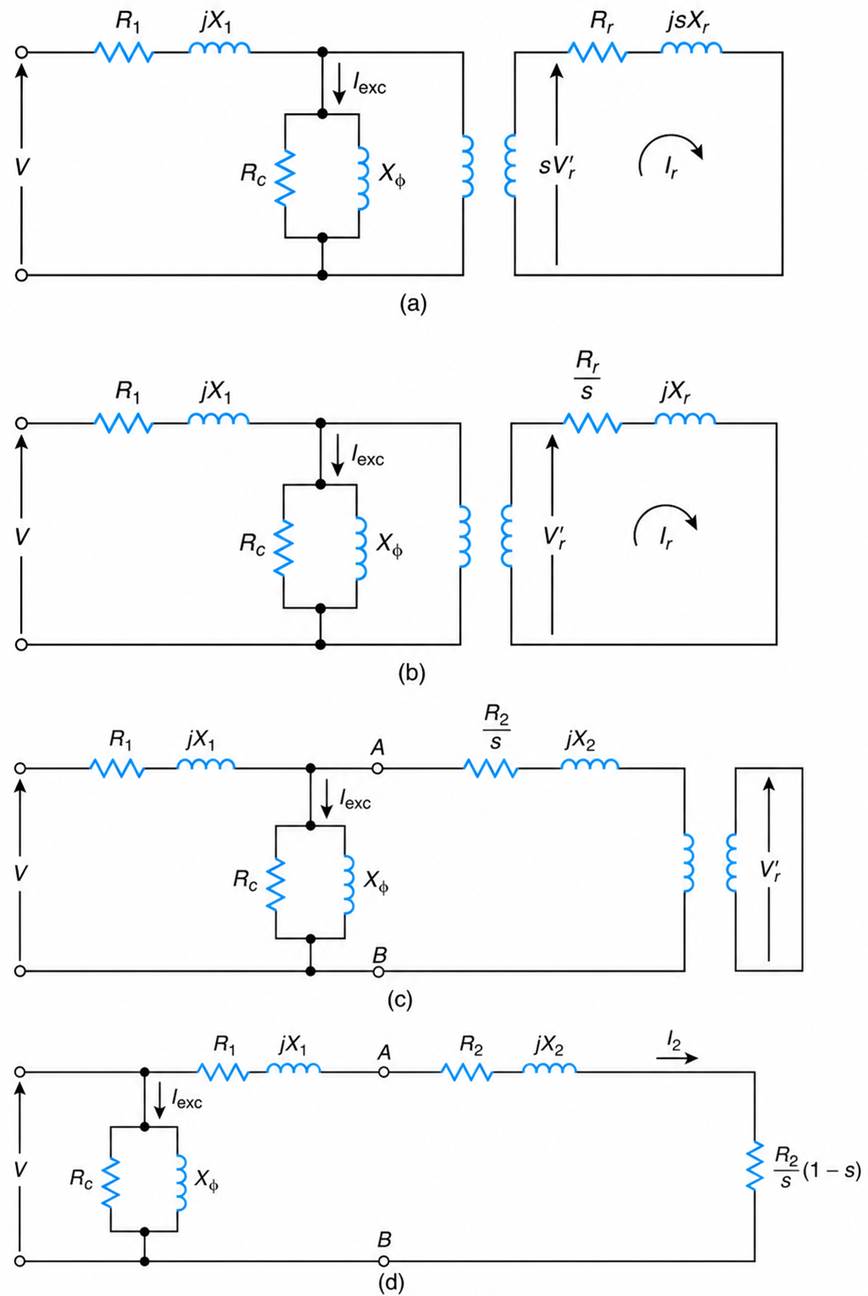
Figure 3-12 Per-phase equivalent circuit of a three-phase induction motor: (a) stator and rotor circuits, (b) equivalent of (a), (c) equivalent of (b), and (d) approximation of (c).
From basic definitions, the per-phase torque developed is
$$T=\frac{\text{power developed}}{\text{actual speed}}=\frac{I_2^{\,2}R_L}{\omega_a} \ \ \ \ \ (3.34)$$
The equivalent mechanical load resistance (RL) is
$$R_L = R_2 \frac{1 - s}{s}$$
and the actual speed is
$$\omega_a = \omega_s (1 - s)$$
Substituting the above into Equation (3.34), we obtain
$$T=\frac{I_2^{\,2}R_2\left(\dfrac{1-s}{s}\right)}{\omega_s(1-s)} \ \ \ \ \ (3.35)$$
$$T=\frac{I_2^{\,2}R_2}{\omega_s s}\ \text{N}\cdot\text{m/phase} \ \ \ \ \ (3.36)$$
From the equivalent circuit, the magnitude of the current I2 is
$$I_2=\left|\frac{V}{Z}\right|=\frac{V}{\sqrt{\left(R_1+\dfrac{R_2}{s}\right)^2+X^2}} \ \ \ \ \ (3.37)$$
where
$X = X_1 + X_2$
From the above, the torque developed in terms of the motor’s parameters is
$$T=\frac{V^2}{\left[\left(R_1+\dfrac{R_2}{s}\right)^2+X^2\right]}\left(\frac{R_2}{\omega_s s}\right)\text{N}\cdot\text{m/phase} \ \ \ \ \ (3.38)$$
where V is the phase-to-neutral voltage.
The variation of torque versus slip is shown in Figure 3-13. The abscissa of this curve is the motor’s speed or slip. The symbols Tfl, Tst , and Tm correspond to the full-load, starting, and maximum torque of the motor, respectively.
The same diagram also shows the torque-speed characteristic of the mechanical load. The intersection of these characteristics gives the operating torque and speed of the motor. For this reason, it is extremely important that, before selecting a suitable motor, you accurately calculate the torque-speed characteristic of the driven load.

Figure 3-13 Typical torque-speed characteristics.
The motor and load torque-speed characteristics are also used to find the accelerating and decelerating times of the motor. These parameters are important for the transient analysis of machines and for the proper selection of the motor’s protective devices.
From Equation (3.38), it is evident that, for a constant slip, the torque is proportional to the applied voltage squared:
$$T\propto V^2 \ \ \ \ \ (3.39)$$
In practice, you may have to evaluate the starting torque capability of a motor because its high starting currents—depending on the impedance of the supply network—reduce the voltage delivered to the stator, and as a result the starting torque is also reduced. When the Thevenin impedance ( Rth+jXth) of the supply network is known, R1 in Equation (3.38) should be replaced by R1+Rth, and X should be replaced by X+Xth.
From Equation (3.38), after expanding and simplifying, we obtain
$$T=\frac{V^2sR_2}{\omega_s\left[(sR_1)^2+2sR_1R_2+R_2^{\,2}+(sX)^2\right]}\ \text{N}\cdot\text{m/phase} \ \ \ \ \ (3.40)$$
For slips in the full-load range, the predominant term in the denominator of the above equations is R22. Therefore,
$$T\approx\frac{V^2}{\omega_s}\frac{s}{R_2} \ \ \ \ \ (3.41)$$
Or
$$T\approx K\frac{s}{R_2} \ \ \ \ \ (3.42)$$
where K is the constant of proportionality given by
$$K=\frac{V^2}{\omega_s} \ \ \ \ \ (3.43)$$
From Equation (3.42), it is evident that in the full-load operating range, the higher the actual speed of the motor, the lower its output torque. It can also be shown that for a certain range of rotor resistance, the starting torque (Tst) of the motor is proportional to its rotor resistance. Mathematically,
$$T_{st}\propto R_2 \ \ \ \ \ (3.44)$$
The higher the rotor resistance, the higher the motor’s starting torque, and the lower its inrush current.
Because of the effects of rotor resistance on starting torque and starting current, the high-power motors supplied through weak power systems (i.e., a supply network with relatively high impedance) are of the wound-rotor type.
Maximum or Breakdown Torque
Refer again to the approximate equivalent circuit of Figure 3-12(d). For maximum power transfer from stator to the rotor-load resistance, the following relationship must be satisfied:
$$\left|R_1+jX\right|=\frac{R_2}{s} \ \ \ \ \ (3.45)$$
Equating the magnitudes of this relationship, we get the equation for the slip of the motor at maximum torque (Smt) :
$$s_{mt}=\frac{R_2}{\sqrt{R_1^{\,2}+X^2}} \ \ \ \ \ (3.46)$$
Where
$X = X_1 + X_2$
Substituting Equation (3.46) into Equation (3.38), after simplification, we find the following expression for the maximum torque developed by the motor:
$$T_m=\frac{V^2}{\left[\left(R_1+\sqrt{R_1^{\,2}+X^2}\right)^2+X^2\right]}\cdot\frac{\sqrt{R_1^{\,2}+X^2}}{\omega_s}\ \text{N}\cdot\text{m/phase} \ \ \ \ \ (3.47)$$
Thus, the maximum torque is independent of rotor resistance. The rotor resistance controls the slip or the speed where the maximum torque occurs. Typical torque-speed characteristics, as a function of rotor resistances, are shown in Figure 3-14.
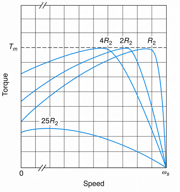
Figure 3-14 Torque-speed characteristics as a function of rotor resistance.
With negligible stator resistance (R1=0) , it can be shown that the torque (T) at any slip (s) is related to the maximum torque (Tm) and its corresponding slip (Smt) by
$$\frac{T}{T_m}=\frac{2ss_{mt}}{s_{mt}^{\,2}+s^2} \ \ \ \ \ (3.48)$$
If the torque-speed characteristic of the motor is not available, then the above equation can be used, in conjunction with some of the motor parameters ( Tst, Tm, Tfl, Sfl) to sketch it.
The torque developed by a motor must be sufficient to provide the motor’s rotational losses and the torque requirements of the mechanical load. The torque requirements of a mechanical load may include any or all of the following torque components:
- the torque component $\left[J\left(\frac{d\omega_a}{dt}\right)\right]$ required to accelerate the rotating masses up to the steady-state speed;
- the torque component $(B\omega_a)$ that represents the viscous friction of the rotating parts; and
- any other torque (TL) requirements of the load.
In mathematical form,
$$T=J\frac{d\omega_a}{dt}+B\omega_a+T_L \ \ \ \ \ (3.49)$$
where
$J =$ the polar moment of inertia of the rotating masses in $\mathrm{N\cdot m\cdot s^2}$
$B =$ the coefficient of viscous friction in $\mathrm{N\cdot m/(rad/s)}$
$T_L =$ a component of load torque in $\mathrm{N\cdot m}$
$\omega_a =$ the actual speed of the motor in $\mathrm{rad/s}$
Equation (3.49) is derived from Newton’s second law of motion for rotating bodies. This law states that the sum of the torques $(\Sigma T)$ about an axis of rotation is equal to the polar moment of inertia (J) times the angular acceleration $(\alpha)$ of the rotating masses. Mathematically,
$$\sum T=J\alpha \ \ \ \ \ (3.50)$$
This law is of primary importance to the dynamic analysis of all machines.
In developing the torque relationships, the magnetizing impedance of the motor was neglected in order to simplify the calculations. The magnetizing impedance, as already mentioned, does not affect the torque of the motor at full load; however, at light loads, it has significant effects.
For accurate torque calculations, the magnetizing impedance should be taken into consideration. You can easily do so by replacing, in Equations (3.38) and (3.47), the voltage source (V) and stator impedance (Z1) by the equivalent Thévenin’s voltage and impedance. Referring to Figure 3-12(c), and looking toward the input from terminals A−B, we obtain
$$V_{th}=\frac{V\left(R_c\parallel jX_{\phi}\right)}{R_1+jX_1+\left(R_c\parallel jX_{\phi}\right)} \ \ \ \ \ (3.51)$$
And
$$Z_{th}=\left(R_1+jX_1\right)\parallel\left(R_c\parallel jX_{\phi}\right) \ \ \ \ \ (3.52)$$
From Equations (3.37) and (3.46), we find that the current I at a slip s is related to the current at maximum torque (Imt) and its corresponding slip (Smt) by
$$\left(\frac{I}{I_{mt}}\right)^2=\frac{2s^2}{s_{mt}^{\,2}+s^2} \ \ \ \ \ (3.53)$$
The equations developed in this section are based on the approximate equivalent circuit of Figure 3-12(d). They are not applicable to motors with deep-bar rotor construction or to double squirrel-cage rotors. In such cases, the proper equivalent circuit should be drawn, then from basic principles, the desired relationships can be derived.
Power Considerations
The power across the air gap (Pag) provides power developed and the rotor copper loss. That is,
$$P_{ag}=I_2^{\,2}R_2\left(\frac{1-s}{s}\right)+I_2^{\,2}R_2 \ \ \ \ \ (3.54)$$
Thus,
$$P_{ag}=I_2^{\,2}\frac{R_2}{s}\ \text{W/phase} \ \ \ \ \ (3.55)$$
As Equation (3.55) shows, the rotor-winding losses are directly proportional to the air-gap power and the operating motor slip. Thus, the smaller the slip, the lower the rotor copper losses. For this reason, the slip, at full load, is usually kept below 5%.
The power developed (Pd) furnishes the output power as well as the rotational losses. Mathematically,
$$P_d=I_2^{\,2}R_2\left(\frac{1-s}{s}\right)\ \text{W/phase}=P_{\text{rotational losses}}+P_{\text{output}} \ \ \ \ \ (3.56)$$
The rotational losses include windage, friction, and stray load losses.
Example 3-3
Figures 3-15(a) and (b) show, respectively, the one-line diagram of a three-phase induction motor and its per-phase equivalent circuit referred to the stator. Assuming constant rotor impedance, and neglecting the effects of the magnetizing current and rotational losses, determine:
a. The number of poles.
b. The synchronous speed of the stator field.
c. The per-unit slip.
d. The line current at starting.
e. The starting torque.
f. The full-load current, power factor, torque, and efficiency.
g. The slip and current at maximum torque.
h. The maximum torque.
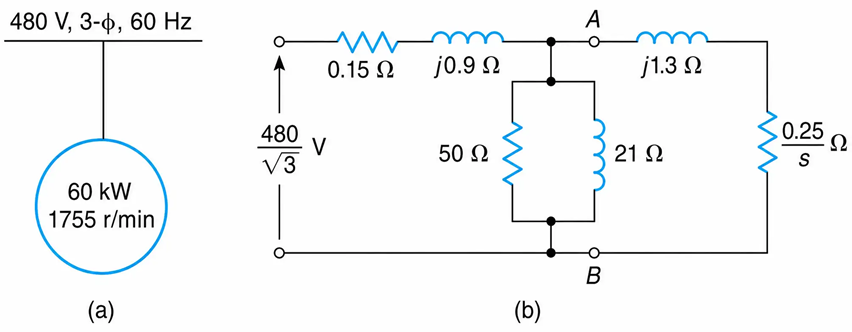
Figure 3-15 Three-phase induction motor one-line diagram and per-phase equivalent circuit referred to the stator
Solution
a. Under normal operating conditions, the slip of a three-phase induction motor is kept small because of its direct relationship to the copper losses. Thus, the actual speed of the motor should be very close to the speed of the synchronously rotating stator field. Since the actual speed is given as 1755 r/min, the closest synchronous speed is 1800 r/min. The number of poles is
$$p=\frac{120\times f}{n_s}=\frac{120\times 60}{1800}=4\ \text{poles}$$
b. The speed of the stator field is
$$n_s = 1800\ \mathrm{r/min}$$
Or
$$\omega_s = 1800\left(\frac{2\pi}{60}\right)=188.5\ \mathrm{rad/s}$$
c. We find that the slip in per unit is
$$s=\frac{n_s - n_a}{n_s}=\frac{1800-1755}{1800}=0.025\ \mathrm{pu}$$
d. The line current at starting is found by applying Ohm’s law in the equivalent circuit of Figure 3-15(c):
$$I_{st}=\frac{480/\sqrt{3}}{0.15+0.25+j2.2}=123.94\angle -79.7^\circ\ \mathrm{A}$$
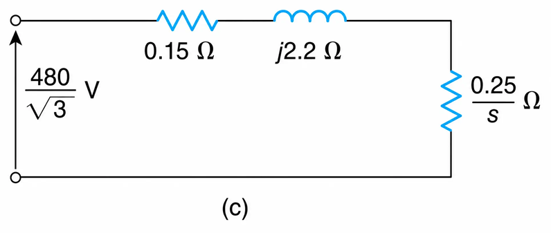
Figure 3-15(c) Equivalent Circuit
e. Since the motor is star-connected and the magnetizing impedance is neglected, the rotor current as seen from the motor terminals is equal to the stator or line current. Substituting the known data into Equation (3.36) gives the motor’s starting torque:
$$T_{st}=3(123.94)^2\frac{(0.25)}{188.5}=61.12\ \text{N}\cdot\text{m}$$
f. The current at full-load isThe current at full-load is
$$I_{fl}=\frac{480/\sqrt{3}}{0.15+\dfrac{0.25}{0.025}+j2.2}=26.68\angle -12.2^\circ\ \mathrm{A}$$
By definition, the power factor is cos12.2°=0.977 lagging. The power factor is unrealistically high because the magnetizing impedance was assumed to be negligible.
The full-load torque is
$$T_{fl}=\frac{3(26.68)^2}{188.5}\left(\frac{0.25}{0.025}\right)=113.32\ \mathrm{N\cdot m}$$
The efficiency of the motor at full-load is
$$\eta=1-\frac{P_{\text{loss}}}{P_{\text{in}}}=1-\frac{3I^2R}{\sqrt{3}\,V_{L-L}I_L\cos\theta}=1-\frac{3(26.68)^2(0.40)}{\sqrt{3}(480)(26.68)(0.977)}=0.96$$
g. From Equation (3.46), the slip at maximum torque is
$$s_{mt}=\frac{0.25}{\sqrt{(0.15)^2+(2.2)^2}}=0.11\ \mathrm{pu}$$
The corresponding motor’s speed is
$$n_a=1800(1-0.11)=1596\ \mathrm{r/min}$$
The current at maximum torque is
$$I=\frac{480/\sqrt{3}}{0.15+\dfrac{0.25}{0.11}+j2.2}=85.99\angle -43^\circ\ \mathrm{A}$$
h. The maximum torque is
$$T_m=\frac{3(85.99)^2(0.25)}{188.5(0.11)}=259.44\ \mathrm{N\cdot m}$$
For purposes of comparison, the results are summarized in Table 3-1.
Table 3-1 Summary of the Results of Example 3-3
|
Operating Condition |
Speed (r/min) |
Current (A) |
Power Factor (Lagging) |
Torque (Nm) |
|
Starting (s = 1) |
0 |
123.94 |
0.18 |
61.12 |
|
Full load (s = 0.025) |
1755 |
26.68 |
0.977 |
113.32 |
|
Maximum torque (sₘₜ = 0.11) |
1596 |
85.99 |
0.73 |
259.44 |
