Single-Phase Motor Working and Equivalent Circuit
Revolving Fields
In Figure 4-1, the mmf of the main winding is
$$\mathcal{F}_{\text{main}}=\mathcal{F}_m\cos(\omega t-\theta) \ \ \ \ \ (4.1)$$
where $\mathcal{F}$ is the maximum value of the mmf produced by the main winding, $\omega$ is the angular frequency of the stator voltage, and $\theta$ is the phase angle of the winding’s impedance.
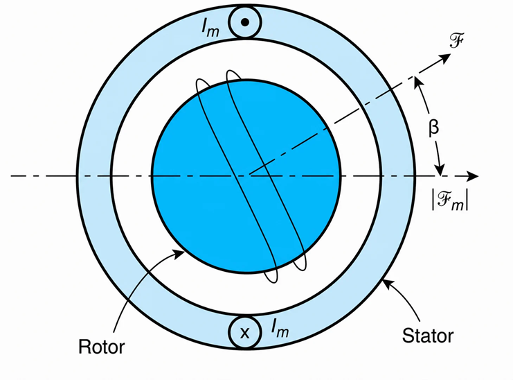
Figure 4-1 Single-phase induction motor.
The field, at an angle of $\beta$ degrees from the axis of the main winding’s mmf, is
$$\mathcal{F}=\mathcal{F}_{\text{main}}\cos\beta \ \ \ \ \ (4.2)$$
From Equations (4.1) and (4.2), we obtain
$$\mathcal{F}=\mathcal{F}_m\cos\beta\cos(\omega t-\theta) \ \ \ \ \ (4.3)$$
From the above, by using the following trigonometric identities,
$$\cos A\cos B=\frac{1}{2}\left[\cos(A+B)+\cos(A-B)\right] \ \ \ \ \ (4.4)$$
we obtain (after rearranging and simplifying),
$$\mathcal{F}=\frac{\mathcal{F}_m}{2}\left[\cos(\omega t+\beta-\theta)+\cos(\beta-\omega t+\theta)\right] \ \ \ \ \ (4.5)$$
Thus, a single-phase motor produces two spacewise oscillatory fields that rotate in opposite directions. The angular speed of the stator fields is designated with $\omega_s$ and is referred to as synchronous speed $(\omega_s=\omega)$.
Rotor Stationary
When the rotor is stationary, the two revolving fields have equal amplitudes and, relative to the rotor, rotate at the same speed but in opposite directions. As a result, no effective field is induced in the rotor windings, and thus the motor does not have a starting-torque capability. For this reason, some domestic fan motors will not start without an external “kicking.” This kicking increases the torque in the direction of the external disturbance, and so the equilibrium of the mmf’s is not maintained. As a result, the motor starts to rotate.
Rotor Turning
When the rotor is turning, the relative angular velocities of the positive and negative fields, with respect to the rotor, are $s\omega_s$ and $(2-s)\omega_s$, respectively. S is the slip of the motor. The two fields induce unequal voltages in the rotor winding. This condition leads to the development of torque as the resulting mmf’s attempt to align their magnetic axes.
Equivalent Circuit of Single-Phase Motor
A single-winding, single-phase motor can be considered as a two-winding, two-phase motor with its auxiliary winding open-circuited. The motor’s equivalent circuit is shown in Figure 4-2. The subscripts 1 and 2 for the voltage, current and impedances designate, respectively, the positive and negative sequence components of the said parameters.
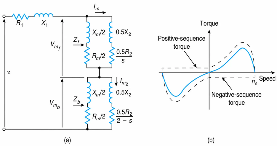
Figure 4-2 Single-phase motor: (a) equivalent circuit, (b) torque-speed characteristic.
The impedance $\left ( R_1+jX_1 \right )$ represents the leakage impedance of the main winding. The magnetizing impedance $Z_m$ and the components of the rotor impedance $\left ( R_2+jX_2 \right )$ are shown as two equal parts connected in series. The justification for this form of equivalent circuit is as follows.
The positive- and negative-sequence components of the currents through the main winding are
$$I_{mf}=I_{mb}=I_m \ \ \ \ \ (4.6)$$
Disregarding the magnetizing impedance, the rotor’s impedances are given by
$$Z_1=0.5X_2+\frac{0.5R_2}{s} \ \ \ \ \ (4.7)$$
$$Z_2=0.5X_2+\frac{0.5R_2}{s-2} \ \ \ \ \ (4.8)$$
where s is the motor’s operating slip. At standstill, the positive-sequence impedance is equal to the negative-sequence impedance.
The positive- and negative-sequence components of the voltage across the rotor impedances are
$$V_{m1}=I_{m1}Z_1 \ \ \ \ \ (4.9)$$
$$V_{m2}=I_{m2}Z_2 \ \ \ \ \ (4.10)$$
At standstill, no voltage is induced in the auxiliary winding. However, when the rotor is turning, $Z_1$ is not equal to $Z_2$, and thus a voltage is induced in the auxiliary winding.
For an accurate analysis, the variation of the rotor’s parameters with the operating slip should be considered.
Torque Developed
The net torque of the motor, as well as its positive- and negative-sequence components, are shown in Figure 4-2(b).
Rewriting the equations for the motor’s torque, we have
$$T=T_f-T_b \ \ \ \ \ (4.11)$$
And
$$T=\frac{I_m^2}{\omega_s}\left(\frac{0.5R_2}{s}-\frac{0.5R_2}{s-2}\right)\,\text{N}\cdot\text{m} \ \ \ \ \ (4.12)$$
Where $I_m$ is the rms value of the main winding’s current and s is the motor’s operating slip in per-unit.
Example 4-1
A 120 V, 60 Hz, four-pole, single-phase induction motor has the approximate equivalent circuit shown in Figure 4-3. When the rotor rotates at 1764 r/min, estimate the torque it develops. Disregard the effects of the magnetizing impedance.
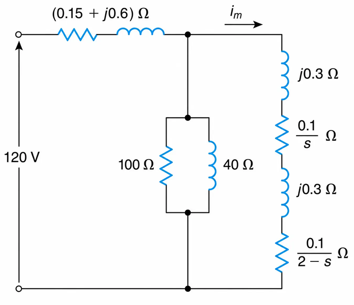
Figure 4-3 Single-Phase Induction Motor Approximate Equivalent Circuit
Solution
At 1764 r/min, the slip is
$$s=\frac{1800-1764}{1800}=0.02\,\text{pu}$$
The impedance of the circuit is
$$Z=0.15+\frac{0.1}{s}+\frac{0.1}{2-s}+j1.2\,\Omega$$
Substituting the operating slip into the above, we obtain
$$Z=0.15+\frac{0.1}{0.02}+\frac{0.1}{2-0.02}+j1.2=5.34\angle13^\circ\,\Omega$$
The current is
$$I=\frac{V}{Z}=\frac{120\angle0^\circ}{5.34\angle13^\circ}=22.48\angle-13^\circ\,\text{A}$$
The torque is calculated by substituting the known parameters into Equation (4.12), as follows:
$$T=\frac{22.48^2}{1800\left(\frac{2\pi}{60}\right)}\left(\frac{0.1}{0.02}-\frac{0.1}{2-0.02}\right)=13.41-0.135=13.27\,\text{N}\cdot\text{m}$$
