Thévenin’s Theorem
Every branch of engineering, depending on the type of problems, developed for their solution some shortcuts referred to as theorems. They are not principles, but techniques to minimize the time it takes to solve a problem. In this section, we will discuss the Thevenin’s theorem.
Thévenin’s theorem states that any network or circuit of the electrical distribution system of a home, factory, and the like, can be represented by a resistance (or impedance) identified as Rth and a voltage source (Vth) in series with the resistance (Figure 1-42).
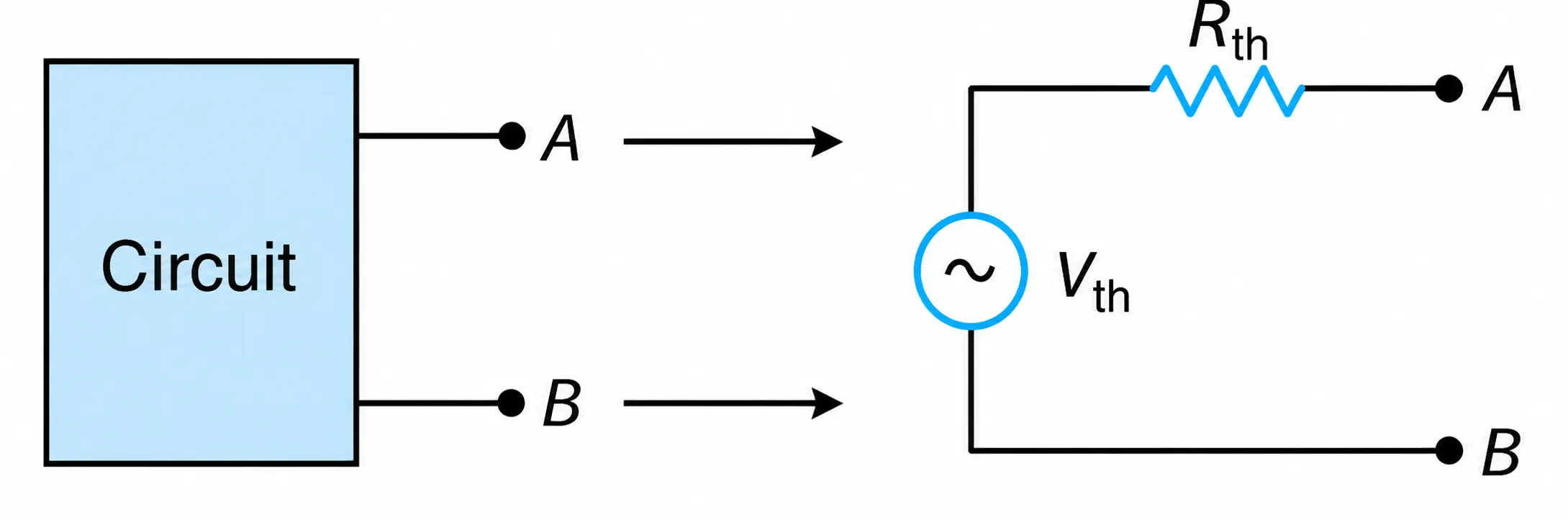
Figure 1-42 Thévenin’s equivalent.
To Find Vth
Open up the terminals under consideration and calculate the voltage across them. In other words, Vth is what a voltmeter will indicate across the open circuit terminals under consideration. ( Rvoltmeter is very high.)
To Find Rth
Discard all independent sources and calculate the resistance looking from the terminals under consideration.
The Thévenin’s equivalent resistance can be also calculated as follows:
$$R_{th} = \frac{V_{oc}}{I_{sc}}$$
where Voc is the open circuit voltage across the terminals under consideration and Isc is the short circuit current through the terminals under consideration.
According to where Thévenin’s theorem is to be applied, the selected terminals may be identified as A-B.
Example 1-16
Refer to Figure 1-43(a). Determine the current through the $5\Omega$ resistor by using Thévenin’s theorem.
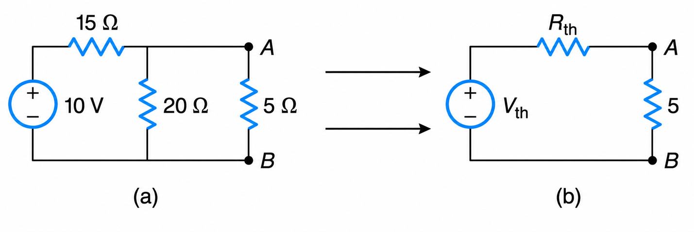
Figure 1-43 (a) Circuit. (b) Equivalent Thévenin’s.
Solution
The terminals across the $5\Omega$ resistor are A–B. To find the Thevenin equivalent seen by this resistor, first remove the $5\Omega$ resistor.
To Find Rth
Deactivate the 10-V voltage source by replacing it with a short circuit. Looking into terminals A–B, the $15\Omega$ and $20\Omega$ resistors are then in parallel.
$$ R_{th}=\frac{15\times20}{15+20}=8.57\,\Omega $$
To Find Vth
With the $5\Omega$ resistor removed, the $15\Omega$ and $20\Omega$ resistors form a voltage divider across the 10-V source.
$$ V_{th}=10\left(\frac{20}{15+20}\right) $$ $$ V_{th}=5.71\,\text{V} $$
Find the current through the $5\Omega$ resistor
The original circuit can now be replaced by its Thevenin equivalent: a 5.71-V source in series with $8.57\Omega$, connected to the $5\Omega$ resistor.
Therefore,
$$ I=\frac{V_{th}}{R_{th}+5} =\frac{5.71}{8.57+5}=0.42\,\text{A}$$
Advantages of Thévenin’s Theorem
- Simplifies complex circuits: Thévenin’s Theorem reduces a complicated linear network into a single equivalent voltage source (V_{th}) in series with an equivalent resistance (R_{th}). This greatly simplifies circuit analysis.
- Makes load analysis easier: Once the Thévenin equivalent is found, different load resistances can be analyzed quickly without repeatedly solving the entire original circuit. This is especially useful in design studies and troubleshooting.
- Useful for power-transfer calculations: The theorem is widely used with the maximum power transfer theorem to determine the load resistance that receives maximum power from a source network.
- Applicable to AC and DC circuits: Thévenin’s Theorem applies not only to DC resistive circuits, but also to AC circuits containing impedances such as inductors and capacitors.
Practical Limitations of Thévenin’s Theorem
- Limited to linear circuits: Thévenin equivalents are valid only for linear networks. Circuits containing strongly nonlinear elements such as diodes and transistors cannot always be represented accurately by a single Thévenin equivalent.
- Valid only at specified terminals: The equivalent circuit reproduces the same voltage-current behavior only from the perspective of the chosen output terminals. Internal circuit behavior is not preserved.
- Power dissipation inside the network changes: Although the external load experiences the same voltage and current, the internal power dissipation of the equivalent circuit may differ from that of the original network.
- Frequency dependence in AC circuits: In AC systems, the Thévenin equivalent impedance changes with frequency because inductive and capacitive reactances vary with frequency. Therefore, one equivalent may not represent the circuit accurately over a wide frequency range.
Applications in Power Systems
- Fault analysis: Power systems are commonly reduced to Thévenin equivalents when calculating short-circuit currents and fault levels at buses and substations.
- Voltage stability studies: Thévenin-based models are used in voltage stability analysis and loadability studies to evaluate how close a power system is to voltage collapse.
- Load-flow simplification: Portions of transmission and distribution networks can be represented by Thévenin equivalents to simplify feeder and bus calculations.
- Protection coordination: Protective relay engineers use Thévenin equivalent impedance to estimate available fault current and coordinate breaker and relay settings.
- Distributed energy resource (DER) studies: Thévenin equivalents help evaluate the interaction of inverter-based resources, microgrids, and utility feeders.
- Maximum power transfer analysis: Thévenin models are used to determine conditions for maximum power transfer between a source network and a load.
Step-by-Step Procedure for Solving a Circuit Using Thévenin’s Theorem
Step 1: Identify the Load
Select the load resistor or load element for which current, voltage, or power must be determined.
Step 2: Remove the Load
Disconnect the load from the circuit, leaving two open terminals.
Step 3: Calculate the Thévenin Voltage ($V_{th}$)
Determine the open-circuit voltage across the two terminals where the load was removed. This voltage is the Thévenin equivalent voltage.
$$V_{th}=V_{OC}$$
Step 4: Calculate the Thévenin Resistance ($R_{th}$)
Deactivate all independent sources:
- Replace ideal voltage sources with short circuits.
- Replace ideal current sources with open circuits.
Then calculate the equivalent resistance seen looking back into the circuit from the open terminals.
Step 5: Draw the Thévenin Equivalent Circuit
Replace the original network with:
- a single voltage source ($V_{th}$)
- in series with a single resistance ($R_{th}$)
Reconnect the load resistor to this simplified circuit.
Step 6: Solve for Load Quantities
Use Ohm’s law and standard circuit relationships to determine load current, voltage, or power.
Load current:
$$I_L=\frac{V_{th}}{R_{th}+R_L}$$
Load voltage:
$$V_L=I_LR_L$$
Load power:
$$P_L=I_L^2R_L$$
