Three-Phase Transformer Connections
Three-phase, two-winding transformers are used to interconnect two distribution systems of different voltages, such as a 25 kV transmission line and a 480 V plant. The majority of industrial transformers are of this type. They are called two-winding transformers because for each primary phase winding, there is only one secondary phase winding. The transformers actually have six coils—three for the incoming three-phase power and three for the output three-phase power.
Three-phase transformers can be either of the core type (Figure. 2-25) or of the shell type as shown in Figure 2-26.
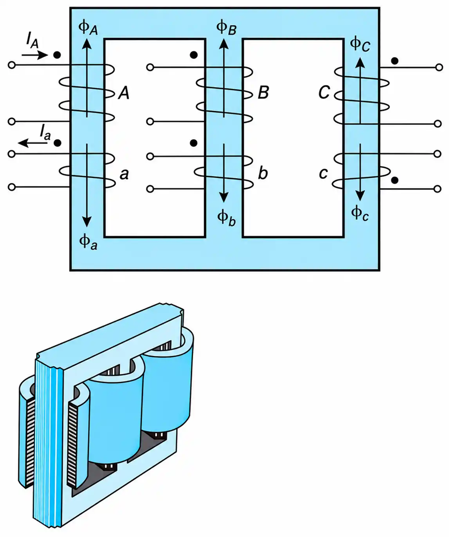
Figure 2-25. Core-type, 3-phase, two-winding transformer.
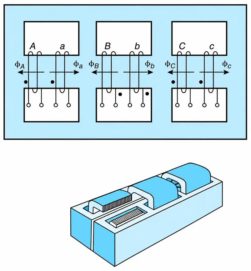
Figure 2-26. Shell-type, 3-phase, two-winding transformer.
Most transformers are of the core type. Their main advantage is that they prevent (ideally, if the phase core branches are identical and leakage is neglected) the presence of the third-harmonic flux, and hence, avoid inducing third-harmonic voltages. They are also less expensive than shell-type transformers of equivalent rating.
Review of Three-Phase Systems
This section reviews the key relationships in three-phase systems needed for transformer analysis, including three-phase power, delta- and star-connected loads, and phase-to-line voltage and current relationships.
Power Considerations
The active (P), reactive (Q), and complex power (S) drawn by a balanced three-phase load are given by
$$P = \sqrt{3}\, V_{L\!-\!L}\, I_L \cos \theta$$
$$Q = \sqrt{3}\, V_{L\!-\!L}\, I_L \sin \theta$$
$$S = \sqrt{3}\, V_{L\!-\!L}\, I_L$$
where VL-L is the rms value of the line-to-line voltage, IL is the rms value of the line current, and $I_L^*$ is its conjugate in phasor form. θ is the phase angle of the load impedance.
When analyzing a three-phase network, it is convenient to draw its power triangle. The real power is taken as reference, and the reactive power is 90 degrees out of phase with it. When the current lags the voltage, the power triangle is drawn leading. In other words, a lagging-power-factor load (which is characteristic of most industrial loads) draws positive VAR, and a leading-power-factor load (capacitive) draws negative VAR (references occasionally differ from this convention).
Current and Voltage Considerations
Depending on the type ($\Delta$, Y) of three-phase connection, the phase and line parameters of a three-phase load are, as shown below, interrelated.
Delta-Connected Load
In a delta-connected load (Figure. 2.27), the line and phase voltages are equal, while the line current lags the phase current by 30°and is larger by a factor of $\sqrt{3}$. Thus,
$$V_{L\!-\!L}=V_{p\!-\!p} \ \ \ \ \ (2.47)$$
$$I_L=\sqrt{3}\,I_p\angle-30^\circ \ \ \ \ \ (2.48)$$
where the subscript p stands for the phase parameters.
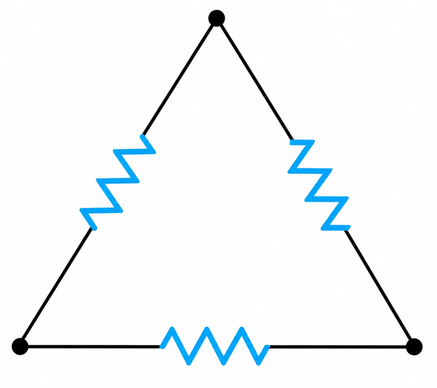
Figure 2-27. Delta-connected load.
Star-Connected Load
In a star-connected load (Figure. 2-28), the line and phase currents are the same, while the line voltage leads the phase voltage by 30° and is larger by a factor of $\sqrt {3}$. Thus,
$$I_L=I_p \ \ \ \ \ (2.49)$$
$$V_{L\!-\!L}=\sqrt{3}\,V_{L\!-\!N}\angle30^\circ \ \ \ \ \ (2.50)$$
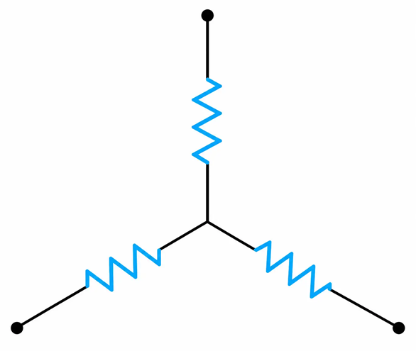
Figure 2-28. Star-connected load.
Equations (2.48) and (2.50) are derived from a voltage phase sequence ABC.
The analysis of three-phase, two-winding transformers is simplified when their per-phase equivalent electric or magnetic circuits are used. The equivalent circuit of one phase is drawn, and the computations are identical to those used for single-phase transformers. Then the standard three-phase system relationships are employed to find the overall transformer parameters, such as currents, voltages, or power.
Phase Shift between Primary and Secondary Voltages
The phase shift, or the angular displacement, between the primary and the corresponding secondary voltage depends on the type of transformer connection. In a delta–delta or a star–star transformer, the angular displacement is zero; in a delta–star or a star–delta transformer, it is 30 degrees. According to the ASA, the voltages on the HV side lead the corresponding voltages on the LV side by 30 degrees, regardless of which side is star or delta.
Magnetic Circuit Analysis
The magnetic circuit approach to the solution of three-phase transformer problems has the advantage of giving a physical insight into what is happening within the transformer. It can be of great assistance in computations involving the unbalanced operation of transformers.
A per-phase magnetic equivalent circuit is shown in Figure. 2-29(c). Neglecting the effects of the exciting current and applying KVL, we obtain
$$N_A I_A=N_a I_a \ \ \ \ \ (2.51)$$
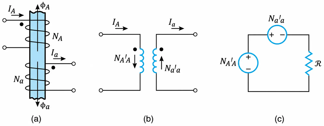
Figure 2-29. Schematic for one phase of a two-winding, three-phase transformer. (a) Polarity of terminals and direction of flux. (b) Relative direction of mmf’s. (c) Magnetic equivalent circuit per phase.
$$\Phi_A=\Phi_a \ \ \ \ \ (2.52)$$
As before, the upper-case subscripts represent the parameter of the primary side, while the lower-case subscripts represent the parameter of the secondary side.
In analyzing problems, it is helpful if the coupled coils, with their actual magnetic volts, are drawn as shown in Figure. 2-29(b).
Electric Circuit Analysis
When electric circuit analysis is used to solve three-phase transformer problems, the following procedure is recommended:
- Draw the per-phase electrical equivalent circuit.
- Determine the turns ratio. This is given by the ratio of the phase to neutral voltages of the primary and secondary windings. This ratio is established by taking into consideration the delta- or star-type winding connection.
- Draw the equivalent star–star connection of the given transformers for delta–star ($\Delta$-Y) or delta–delta $(\Delta\!-\!\Delta)$ type of winding connection. This is easily accomplished by using the standard delta–star equivalent impedances. That is,
$$Z_y=\frac{Z_{\Delta}}{3} \ \ \ \ \ (2.53)$$
Where ZΔ and Zy represent, respectively, the equivalent impedances connected in delta and star. The above relationship is applicable only when the per-phase winding impedances are identical. When the winding impedances are unequal, changing a delta-connected load to its equivalent star.
- Select the reference voltage from the given data of the problem. Recall that when the transformer is connected delta–star or star–delta, the HV line-to-line voltages lead the corresponding LV line-to-line voltages by 30 degrees.
One-Line Diagram
Three-phase transformer coils can be connected in either star (Y) or delta (Δ) configure rations. Figure 2-30(a) shows the industry’s standard terminal identification for two-winding, three-phase transformers. The letters H and X represent high and low voltage, respectively, and the subscripts 1, 2, and 3 correspond to phases 1, 2, and 3, or phase rotation ABC. The subscript 0 is used to designate the grounded terminal of a star-connected transformer. The neutral conductor of the system is also connected to this point when a four-wire distribution system is required. A star–star connected three-phase, two-winding transformer has, on the HV and LV windings, four terminals to which as many as five conductors can be connected.
The three conductors correspond to the 3-phase power cables, the fourth conductor constitutes the neutral of the system, and the fifth conductor is the ground of the transformer tank. The neutral is required when single-phase loads are to be supplied with line-to-neutral voltage. The ground and the neutral conductors are shown dotted in order to differentiate them from the other three main cables.
The neutral is an insulated cable and carries current under normal operating conditions, while the ground conductor is usually not insulated and carries no current under normal operating conditions. However, when one of the phases of a grounded equipment is accidentally grounded, the resulting high short-circuit current will flow through the ground cable.
In the one-line diagram (Figure. 2-30(b)), the type of winding connections ( Δ or Y) is shown. The first symbol indicates the primary or incoming terminal connection, and the second the outgoing or secondary terminal coil connection. The kVA, voltage, and impedance ratings are also marked on the one-line diagram.
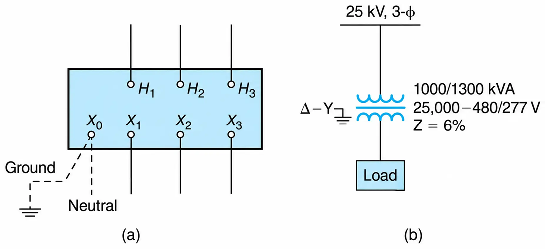
Figure 2-30. Three-phase, two-winding transformers. (a) Terminal identification. (b) One-line diagram representation of a 1000/1300 kVA, 25,000–480/277 V.
When the transformer is manufactured with special insulation, or equipped with fans, it can transform higher kVA without having its life expectancy reduced. Transformers equipped with one set of ventilating fans cost about 5% more but can deliver 33% more current at nominal voltages. Figure. 2-31 shows a substation transformer equipped with ventilating fans.
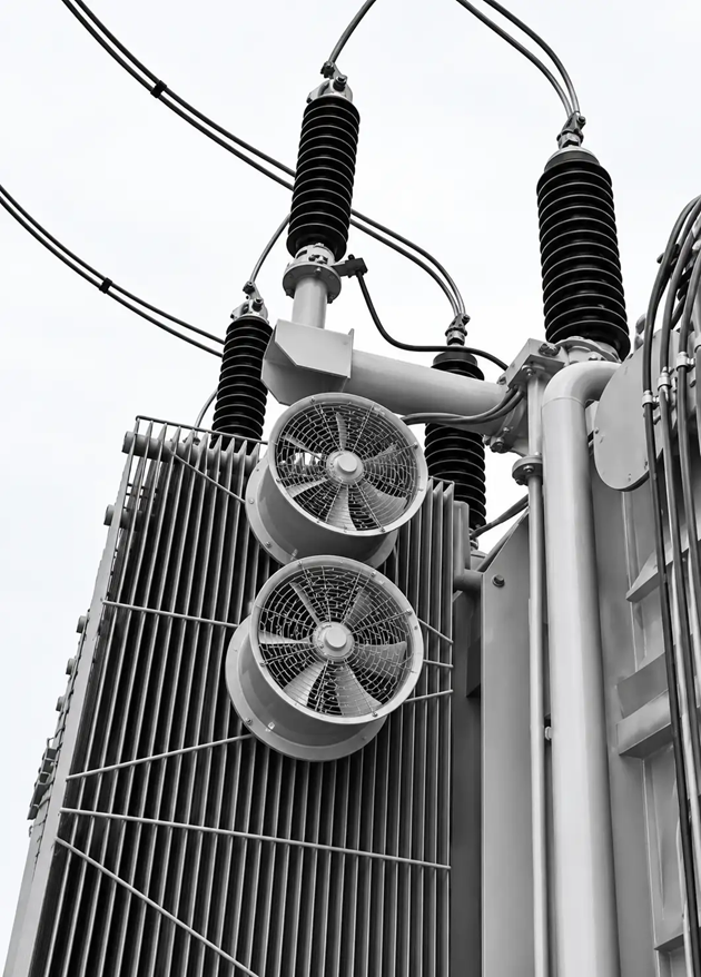
Figure 2-31. Transformer with ventilation fans.
The per-unit impedance shown in the one-line diagram is calculated using the base kVA power of the transformer.
Types of Three-Phase Transformers
The following type of three-phase, two-winding transformers will be analyzed:
- $\Delta-Y$
- $\Delta-\Delta$
- $Y-\Delta$
- $Y-Y$
- $2\text{-}\phi\ \text{to}\ 3\text{-}\phi$
- $1\text{-}\phi\ \text{to}\ 3\text{-}\phi$
Delta–Star Transformers
Typical $\Delta-Y$ transformers are shown in Figure 2-32 and Figure 2-33. The $\Delta-Y$ type of three-phase transformers are very popular because they:
- Provide three-phase (L-L-L), one-phase (L-L), and L-N loads. The latter are necessary for computers, general usage receptacles, and the like.
- Provide means of grounding the neutral terminal which stabilize the reference voltage and can be used—through an impedance—to limit the L-G short-circuit current and thus contribute to mitigation of fires, danger to personnel, and cost of upstream current protective devices.
- Prevent the load’s harmonic current components to circulate to the transformer’s supply power lines.
- Are relatively more economical and have faster delivery.
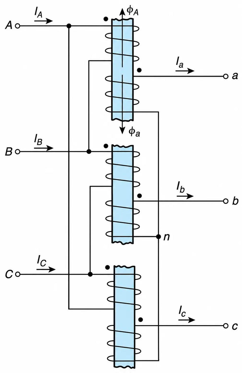
Figure 2-32. Three single-phase transformers connected $\Delta-Y$ to form a two-winding, three-phase transformer bank.
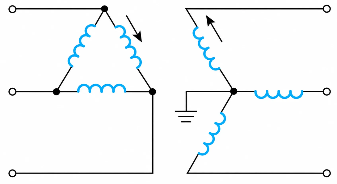
Figure 2-33. Delta–Star Transformer Winding Connection
Relatively speaking, the $\Delta-Y$ transformer maintains sinusoidal line-to-line waveforms in the primary and secondary windings.
The $\Delta$-connected winding provides a short circuit to the flow of third harmonics. The zero-sequence current components produced by the unbalanced loads, and the third harmonics of the nonsinusoidal magnetizing current are in phase for each winding and can circulate within the $\Delta$-connected circuit.
The star-connected winding is subjected to $\frac{1}{\sqrt{3}}$ of the line-to-line voltage, and thus reduced insulation is required for the transformer windings.
One disadvantage of the $\Delta-Y$ transformer is that it cannot be paralleled with a Y-Y transformer. The transformer’s line-to-line voltages are in phase in the high-and low-voltage sides, while the corresponding $\Delta-Y$ line-to-line voltages between primary and secondary are $30^\circ$ apart. This phase difference is undesirable for parallel operation. It results in large circulating currents, which reduce the kVA output capability of the paralleled transformers.
Example 2-5
For the three-phase transformer shown in the one-line diagram of Figure 2-34(a), determine:
a. The ohmic value of its reactance referred to the low- and high-voltage windings.
b. The magnitude of the short-circuit current in the transformer windings when a three-phase short takes place across the transformer’s secondary terminals.
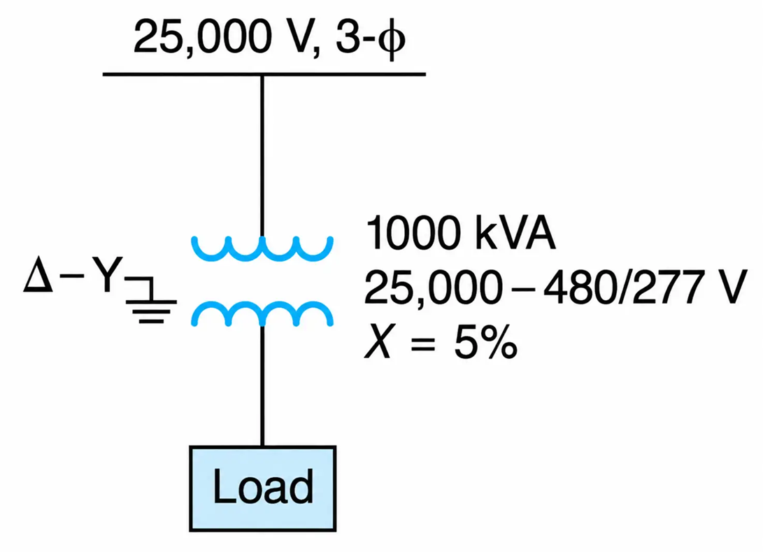
Figure 2-34(a). Three-Phase Transformer one-line diagram
Solution
a. The base parameters for the per-unit calculations are obtained from the rating of the transformer:
$$S_b=1000\ \text{kVA}$$
$$V_{bH}=25\ \text{kV},\qquad V_{bL}=480\ \text{V}$$
$$Z_{bH}=\frac{(25.0)^2}{1.0}=625\ \Omega/\text{phase},\qquad Z_{bL}=\frac{(0.48)^2}{1.0}=0.23\ \Omega/\text{phase}$$
$Z_{bH}$ is the equivalent star-connected impedance in $\Omega/\text{phase}$. The base currents are
$$I_{bH}=\frac{1000}{\sqrt{3}\times25}=23.09\ \text{A},\qquad I_{bL}=\frac{1000}{\sqrt{3}(0.48)}=1202.81\ \text{A}$$
Then the ohmic values of the reactances are
HV Winding
$$X_H=0.05(625)=31.25\ \Omega/\text{phase},\ \text{star equivalent}$$
LV Winding
$$X_L=0.05(0.23)=0.012\ \Omega/\text{phase},\ \text{star equivalent}$$
The short-circuit current can be found by using any of the following methods.
LV Winding
Applying Ohm’s law in the circuit of Figure 2-34(b), we find that the magnitude of the current in the LV winding is
$$I=\frac{V}{X}=\frac{480/\sqrt{3}}{0.012}=24,056.26\ \text{A}$$
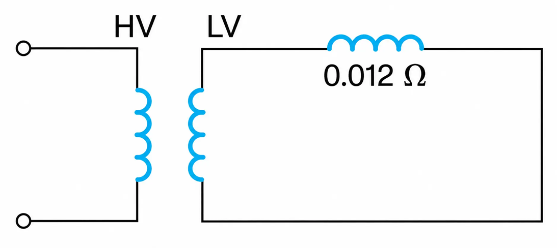
Figure 2-34(b). Equivalent Circuit
Using per-unit values:
$$I=\frac{1.0}{0.05}=20\ \text{pu}$$
$$=20(1202.81)=24,056.26\ \text{A}$$
HV Side
Applying Ohm’s law in the star equivalent circuit of Figure 2-34(c), we obtain the magnitude of the short-circuit current in the HV windings:
$$I=\frac{V}{X}=\frac{25,000/\sqrt{3}}{31.25}=461.88\ \text{A line current}$$
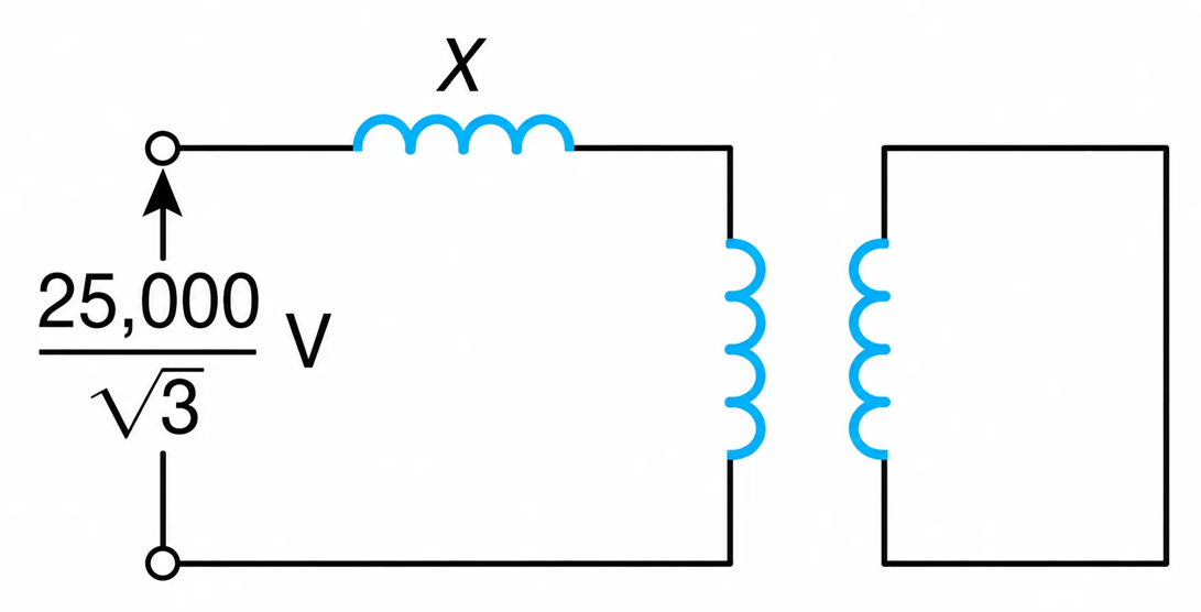
Figure 2-34(c). Star (Y) Equivalent Circuit
The magnitude of the phase current is
$$I_p=\frac{461.88}{\sqrt{3}}=266.67\ \text{A}$$
Using Ohm’s law, for the delta-connected equivalent circuit, we obtain
$$X_{\Delta}=3X_Y=3(31.25)=93.75\ \Omega$$
$$I_p=\frac{25,000}{93.75}=266.67\ \text{A}$$
and
$$I_L=\sqrt{3}(266.67)=461.88\ \text{A}$$
Refer to Figure 2-34(d). By using the current transformation property of transformers, we obtain
$$I_p=24,056.26\frac{480/\sqrt{3}}{25,000}=266.67\ \text{A}$$
and
$$I_L=\sqrt{3}\,I_p=461.88\ \text{A}$$
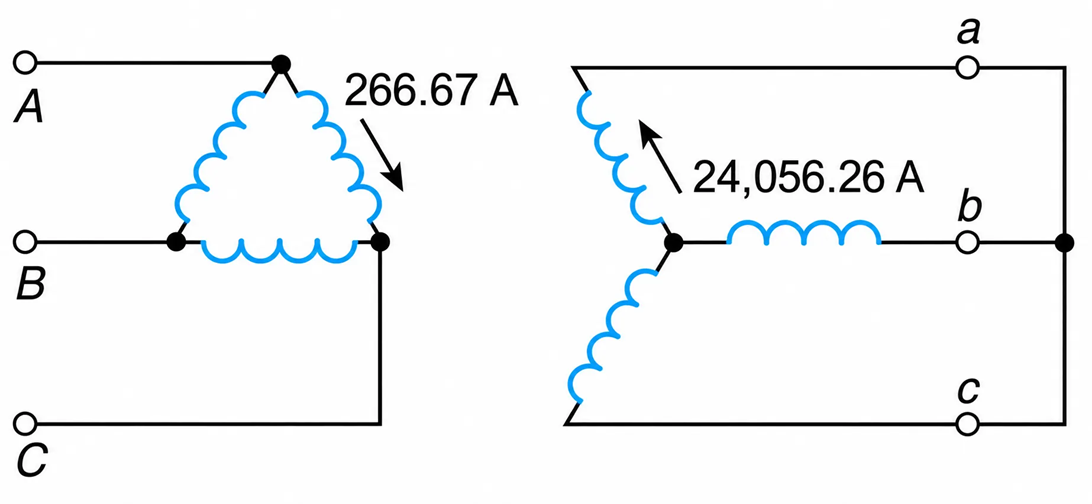
Figure 2-34(d). Delta-Y Transformer Connection
Example 2-6
Three identical single-phase transformers, each of 500 kVA, 4160–480 V, 60 Hz, are connected $\Delta-Y$ to form a 3-phase transformer bank. Data for the short-circuit test on one of the single-phase transformers is as follows:
Low-voltage winding shorted:
$$V_H=250\ \text{V},\qquad I_H=120.19\ \text{A},\qquad P=10\ \text{kW}$$
The transformer, as shown in Figure 2-35(a), is connected to an upstream substation of 4160 volts through a feeder whose impedance is (0.2 + j0.4) ohms per phase. When the transformer delivers rated current at 0.9 power factor lagging, determine:
- The line-to-line voltage across the load.
- The power supplied by the upstream substation.
- The current through the transformer windings when a 3-phase short takes place at the secondary terminals of the transformer.
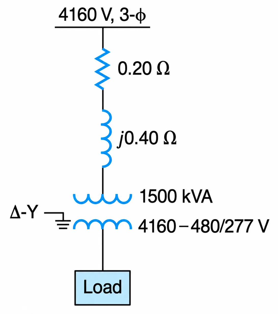
Figure 2-35(a). Transformer Single-Line Diagram
Solution
From the short-circuit test data, we get
$$|Z_{eH}|=\frac{250}{120.19}=2.08\ \Omega/\text{phase}$$
$$R_{eH}=\frac{10,000}{(120.19)^2}=0.69\ \Omega/\text{phase}$$
$$X_{eH}=\sqrt{2.08^2-0.69^2}=1.96\ \Omega/\text{phase}$$
Thus,
$$Z_{eH}=0.69+j1.96$$
$$=2.08\angle70.6^\circ\ \Omega/\text{phase}$$
This is the per-phase impedance referred to the HV winding, which is delta connected. In order to simplify the calculations of the primary, as shown in Figure 2-35(c), it is changed to an equivalent star. Then the per-phase equivalent circuit, as seen from the HV winding, is shown in Figure 2-35(d).
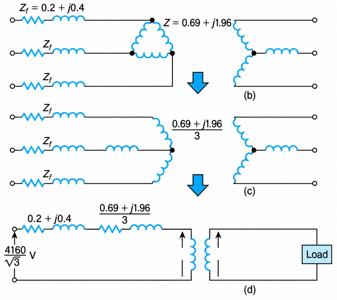
Figure 2-35 (b), (c), and (d). Per-Phase Impedance referred to the HV winding
The magnitude of the line current in the primary of the $\Delta-Y$ transformer is
$$I=\frac{1500}{\sqrt{3}(4.160)}=208.18\ \text{A}$$
Refer to Figure 2-35(d). The total impedance in the primary circuit is
$$Z=0.2+j0.4+\frac{0.69+j1.96}{3}=1.14\angle67.8^\circ\ \Omega/\text{phase}$$
Applying KVL to the per-phase equivalent circuit of Figure 2-35(d), we obtain
$$V_1\angle0^\circ=\frac{4160}{\sqrt{3}}\angle\beta_1-208.18\angle-25.8^\circ(1.14\angle67.8^\circ)$$
$$=\frac{4160}{\sqrt{3}}\angle\beta_1-237\angle41.9^\circ$$
Equating the imaginary parts, we obtain
$$\beta_1=\arcsin\left(\frac{\sqrt{3}}{4160}(237\sin41.9^\circ)\right)=3.8^\circ$$
Equating the real parts, we get
$$V_1=\frac{4160}{\sqrt{3}}\cos3.8^\circ-237(\cos41.9^\circ)=2220.21\ \text{V/phase}$$
The voltage across the secondary of the transformer is
$$V_2=V_1\left(\frac{480}{4160}\right)=2220.21\left(\frac{480}{4160}\right)=256.18\ \text{V/phase}$$
$$=(256.18)\sqrt{3}=443.71\ V_{L-L}$$
The power supplied is
$$P=\sqrt{3}\,V_{L-L}I_L\cos\theta$$
$$=\sqrt{3}(4160)(208.18)\cos(3.8^\circ+25.8^\circ)$$
$$=1303.96\ \text{kW}$$
The magnitude of the short-circuit current through the feeder is
$$I_L=\frac{V}{Z}=\frac{4160}{\sqrt{3}(1.14)}=2109.60\ \text{A}$$
The current in the $\Delta$-connected windings is
$$I_P=\frac{I_L}{\sqrt{3}}=\frac{2109.60}{\sqrt{3}}=1218\ \text{A}$$
The current in the Y-connected windings is
$$I_s=(1218)\frac{4160}{480/\sqrt{3}}=18,283.20\ \text{A}$$
Alternatively, using per-unit values,
$$Z_{bH}=\left(\frac{4160}{1.5}\right)^2=11.54\ \Omega/\text{phase}$$
Thus,
$$Z_{e,\text{pu}}=\frac{1.14}{11.54}=0.099\ \text{pu}$$
$$I_{sc}=\left(\frac{1}{0.099}\right)=10.13\ \text{pu}$$
In the LV side:
$$I_{sc}=10.13\frac{1500}{\sqrt{3}(0.480)}=18,283.20\ \text{A}$$
In the HV side:
$$I_{sc}=10.13\frac{1500}{\sqrt{3}(4.16)}=2109.60\ \text{A}$$
$\Delta-\Delta$ Transformer
A $\Delta-\Delta$ winding connection is shown in Figure 2-38. This type of transformer has the following advantages:
- When a line-to-ground fault—the most common type of fault—occurs in the secondary distribution of the transformer, the resulting current is very small and therefore the power flow is not interrupted. This is of tremendous importance to industries whose processes—such as the melting of metals—cannot be interrupted.
- This type of transformer connection maintains sinusoidal voltages at its output terminals. This is because the delta–delta winding connection provides a path for the flow of the third harmonic component of the magnetizing current and for the circulation of the zero-sequence component of the unbalanced load currents.
- When three single-phase transformers are connected in $\Delta-\Delta$ to form a 3-phase transformer bank, one of the single-phase transformers can be removed and the resulting open-delta or VEE transformer bank can deliver about 58% of its original rating to a three-phase secondary load.
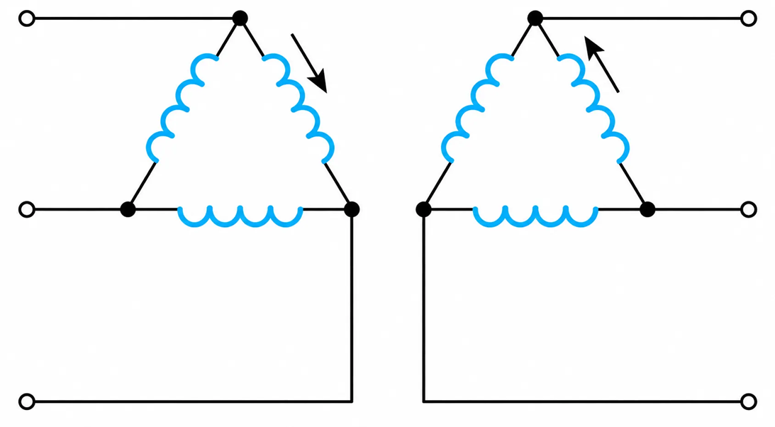
Figure 2-38. Delta–Delta Transformer Winding Connection
In such operations, the transformer is referred to as a V-type or open-delta type of transformer.
From the theory of three-phase circuits, the per-phase current $\left(I_P\right)$ is related to the line current $\left(I_L\right)$ by the $\sqrt{3}$. That is,
$$I_P=\frac{I_L}{\sqrt{3}}$$
When one of three-single-phase transformers fails, the secondary winding phase currents are equal to line currents that were originally designed to carry only 58% of the line current.
The additional advantage of the delta–delta transformer is that it will continue to operate while there is a line-to-ground short circuit.
The disadvantage of this type of winding configuration is that it cannot supply L–N single-phase loads.
Star–Delta Transformer
The $Y-\Delta$ transformer is of limited use because it does not provide a grounded neutral and thus does not support L-N, single-phase loads.
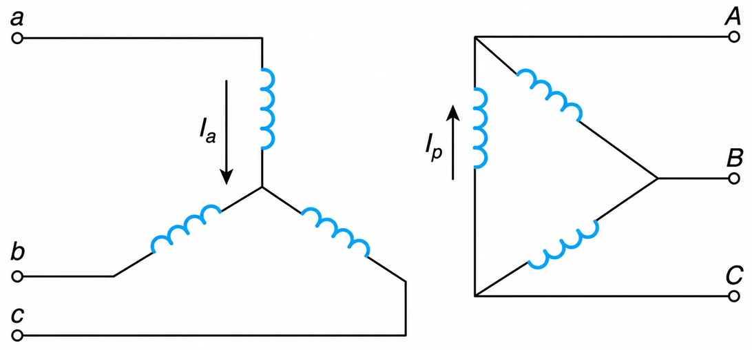
Figure 2-39. Y-Δ Transformer Winding Connection
Star–Star Transformer
The Y-Y transformer, when the star-point is grounded, can provide L–L–L, L–L, and L-N loads. However, it permits the flow harmonic current through the upstream and downstream network.
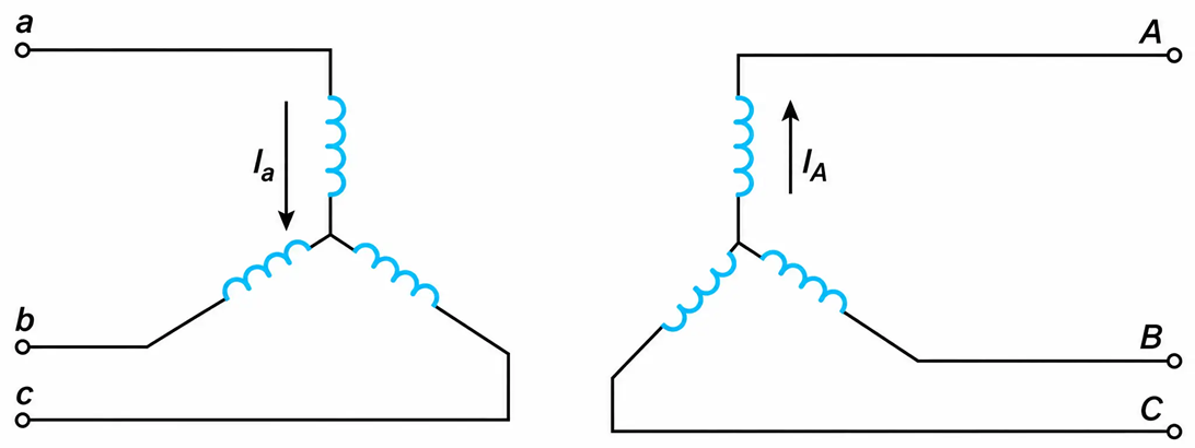
Figure 2-40. Y-Y Transformer Winding Connection
An ungrounded Y-Y transformer is shown in Figure 2-41. When the transformer’s load is slightly unbalanced, the neutral points (n) may not be at a fixed potential with respect to ground. This is referred to as the “floating” neutral. The potentially unstable neutral is due mainly to unbalanced load currents.
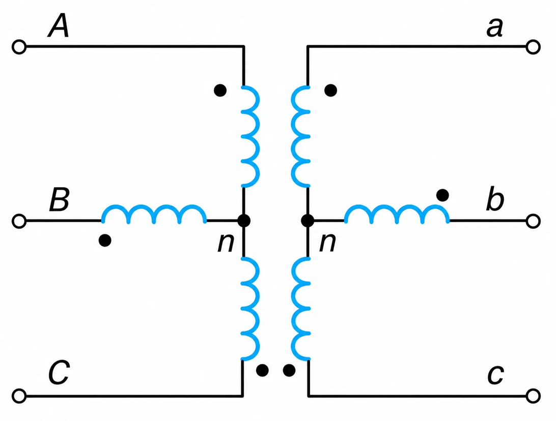
Figure 2-41. Ungrounded star–star (Y-Y) connected transformer.
Considering Figure 2-41, from KVL, in the primary side, we have
$$V_{Cn}+V_{nA}+V_{AC}=0$$
Or
$$V_{AC}=V_{nC}+V_{An}$$
The potential $V_{AC}$ is constant, owing to the primary voltage source. The other voltages ( $V_{nC}$ and $V_{An}$ ) will vary in a way that satisfies the previous two equations.
To stabilize the potential of the neutral point, a delta-connected winding—the so-called tertiary—is wound on the core of the transformer. In this case, the transformer becomes a three-phase, three-winding transformer. Such transformers have high MVA ratings and are normally used by the utilities.
Example 2-7
Show that, when a single-phase load is connected from one line to neutral in the secondary of an ungrounded Y-Y, 3-phase transformer, the voltage across the loaded phase is reduced while the other voltages from line-to-neutral will be increased.
Solution
Assume a load is connected from line “a” to neutral, as shown in Figure 2-42. The load impedance will draw a current $I_a$ because of the voltage induced in the secondary winding:
$$I_a=\frac{V_a}{Z}$$
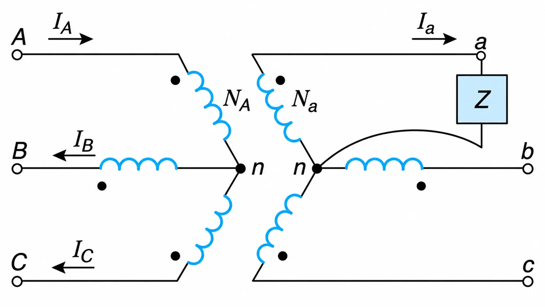
Figure 2-42. Y-Y 3-phase transformer
Since there is a current on the secondary means, there must also be a current $I_A$ in the primary, because of the current-transformation property of transformers, namely:
$$N_A I_A=N_a I_a$$
Applying KCL, in the primary winding, we have
$$I_A=I_B+I_C$$
$I_A$ exists, and, since, $I_b=I_c=0$ then $I_B$ and $I_C$ must represent increases in the exciting currents in phases B and C, respectively. Thus, their corresponding voltages $V{Bn}$ and $V{Cn}$ must also be increased. This leads to the reduction of $V_{AB}=\left(V_{AB}=V_{nB}+V_{An}\right)$ and $V_{aB}$.
Exercise
Compare and contrast the $\Delta-\Delta$ and $\Delta-Y$ type of three-phase, two-winding transformers. Consider insulation levels, exciting currents, and output voltage waveforms.
| Parameter | $\Delta-\Delta$ | $\Delta-Y$ |
| Insulation level of secondary winding | Nominal | Lower for Star Winding |
| Exciting Current | Non-Linear | Non-Linear |
| Output voltage waveforms | Sinusoidal | Sinusoidal |
Special Type of Transformers
This section describes the transformers that change a 2-phase and 1-phase voltage supply to a 3- balanced system. These special transformers may be analyzed by drawing their corresponding magnetic equivalent circuits in terms of their mmf’s.
Scott-Connection
A Scott-transformer connection, as shown in Figure 2-43, is used to interconnect a 2-phase system to a 3-phase distribution network. The 2-phase voltages are equal in magnitude and at 90 electrical degrees to each other.
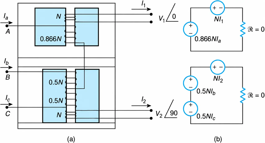
Figure 2-43. Scott-type of transformer. (a) Winding configuration. (b) Equivalent magnetic circuits.
Such transformers have two cores, and in the 3-phase side, one of the windings has 0.866 N number of turns and is connected to the center tap of the other winding, which has N number of winding turns. This winding arrangement insures a 120-degree phase shift among the voltages of the 3-winding.
Refer to Figure 2-43. Assuming an equal number of winding turns (N), we have:
Winding One
Neglecting the core losses and applying KVL in the magnetic circuit of winding 1, we obtain
$$NI_1=0.866\,NI_a$$
Or
$$NI_1=0.866\,NI_a\angle0^\circ$$
Similarly, for winding 2, we obtain
$$NI_2+0.5\,NI_b-0.5\,NI_c=0$$
Or
$$NI_2=0.5N\left(I_c-I_b\right)$$
The magnitudes of the line currents $I_a$, $I_b$, $I_c$ and are equal:
$$NI_2=0.5NI_a\left(1\angle120^\circ-1\angle-120^\circ\right)$$
$$=0.866NI_a\angle90^\circ$$
Thus the mmf’s on the two windings are equal in magnitude and at 90 electrical degrees to each other.
1-phase to 3-phase Transformation
Figure 2-44 shows the winding configuration of a special transformer that is used to change a single-phase line-to-line voltage to a three-phase balanced voltage supply.
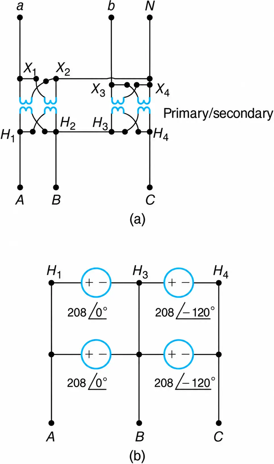
Figure 2-44. One-phase to three-phase transformation. (a) Winding configuration. (b) Equivalent electrical circuit (ideal).
These types of transformers are for economical reasons used within a plant to supply a remote 3-phase panel. The savings result by using two wires instead of three wires.
For a 208 V line-to-line supply voltage, we have
$$V_{ab}=208\angle30^\circ\ \text{V},\qquad V_{an}=120\angle0^\circ,\qquad V_{bn}=120\angle-120^\circ\ \text{V}$$
The transformer’s winding turns ratio is such as to develop 208 V across the secondary windings. That is,
$$V_{AB}=208\angle0^\circ,\qquad V_{BC}=208\angle-120^\circ\ \text{V}$$
The electrical equivalent circuit is shown in Figure 2-42(b). For simplicity,
$$K=208\ \text{V}$$
The voltage $V_{CA}$ can be obtained graphically or by applying KVL in the loop:
$$C-A-H1-H2-H3-H4-C$$
Thus,
$$V_{CA}+K\angle0^\circ+K\angle-120^\circ=0$$
from which
$$V_{CA}=K\angle120^\circ$$
$$=208\angle120^\circ\ \text{V}$$
Due to leakage impedances and a slightly unequal turns ratio, there would be circulating currents. As a result, the efficiency of such transformers is lower than that of their equivalent standard units.
Harmonics of the Exciting Current
Consider the exciting current of one phase only. Neglecting its fourth and higher-order harmonics, we have
$$i_{exc}=i_1+i_2+i_3=I_{m1}\cos\omega t+I_{m2}\cos2\omega t+I_{m3}\cos3\omega t \ \ \ \ \ (2.54)$$
where $I_{m1}$, $I_{m2}$, and $I_{m3}$ are the maximum values of the fundamental, second, and third harmonics.
Second Harmonics
Designating as the maximum value of the second harmonic in one phase, we see that the vectorial sum for all three phases is
$$i_2=I_{m2}\cos2\omega t+I_{m2}\cos2(\omega t+120^\circ)+I_{m2}\cos2(\omega t+240^\circ) \ \ \ \ \ (2.55)$$
From the above:
$$i_2=0$$
Thus, the sum of the second, or even, harmonics of a three-phase system is equal to zero, regardless of the transformer winding connections.
Third Harmonic
The third harmonic components of the exciting current in the lines of a three-phase system do not add up to zero, as in the case of the fundamental and second harmonics. Mathematically,
$$i_3=I_{m3}\cos3\omega t+I_{m3}\cos3(\omega t+120^\circ)+I_{m3}\cos3(\omega t+240^\circ) \ \ \ \ \ (2.56)$$
From the above,
$$i_3=3I_{m3}\cos3\omega t \ \ \ \ \ (2.57)$$
When third harmonics are permitted to flow, the exciting current is nonsinusoidal in waveform. This waveform—as can be verified by the B-H characteristic of high-permeability magnetic materials—is accompanied by sinusoidal flux. Sinusoidal flux produces sinusoidal secondary voltages, and nonsinusoidal flux produces nonsinusoidal secondary voltages.
These nonsinusoidal voltages are undesirable because they may cause electrical apparatuses—motors, computers, and the like—to malfunction. Thus, it is desirable that the waveform of the exciting current be nonsinusoidal.
The nonsinusoidal waveform of the exciting current is ensured when the transformer connections permit the flow of third harmonics.
- Star-connected windings with a grounded neutral provide a physical link so that the harmonics can flow from the system’s lines down to ground, then eventually return to the generator’s grounded neutral. Therefore, star-grounded windings permit the flow of nonsinusoidal excitation currents, and so their secondary phase voltages are sinusoidal.
- Delta-connected windings also produce sinusoidal fluxes and voltages because they permit the third harmonics to circulate within their windings.
In contrast, ungrounded star-connected windings do not permit the flow of third harmonics of exciting currents, and thus the induced voltages are nonsinusoidal.
