Single Phase Motor Starting Methods
A single-phase induction motor can be started in several ways. In addition to the main winding, the motor’s stator includes a starting, or auxiliary, winding. The motor’s cost and its method of starting depend on the configuration of this auxiliary winding. The starting winding is always connected in parallel with the main winding. Because it has higher impedance than the main winding, the starting winding draws less current. The motor’s starting torque depends on the impedance of its windings at standstill and on the effective turns ratio between the stator and rotor windings. Motors equipped with a starting winding are often referred to as “split-phase induction motors.”
The various types of split-phase induction motors are described in the following section.
Auxiliary Winding, Permanently Connected
A split-phase motor with a permanently connected auxiliary winding is shown in Figure 4-4(a). The auxiliary winding may—or may not—include a capacitor. The capacitor, depending on its relative size, will further increase the starting and full-load torques of the motor. A motor with a permanently connected auxiliary winding does not need any maintenance and is used where a low starting torque is required, such as in the operation of a small ventilating fan.
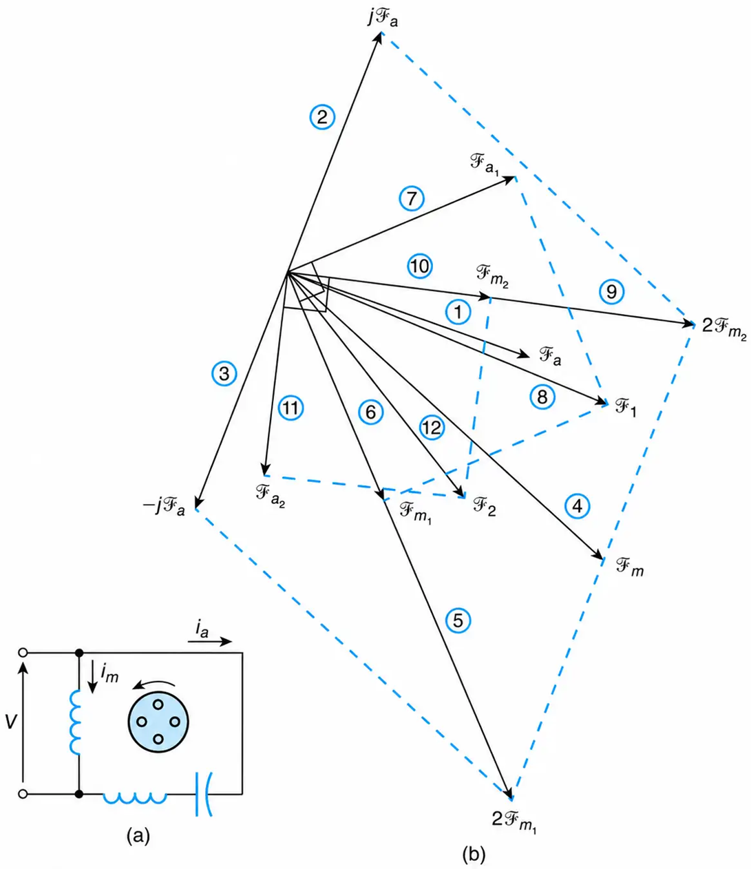
Figure 4-4 Single-phase motor: (a) auxiliary winding, permanently connected, (b) phasor diagram.
Phasor Diagram
The phasor diagram of a split-phase motor with a permanently connected auxiliary winding is shown in Figure 4-4(b). The phasor diagram is constructed by following the sequence identified by the encircled numbers.
Phasors (1), (2), and (3)
The mmf of the auxiliary winding $(\mathcal{F}_a)$ is arbitrarily drawn as shown. When this phasor is rotated by plus and minus 90o, it gives the phasors $(j\mathcal{F}_a)$ and $(-j\mathcal{F}_a)$, respectively.
Phasors (4), (5), and (6)
The mmf of the main winding $(\mathcal{F}_m)$, relative to that of the auxiliary winding, is larger and more inductive. Its phasor is drawn as shown.
Phasors (7) and (8)
The positive-sequence components of the main and auxiliary windings are equal to each other in both magnitude and phase quadrature. The algebraic summation of the positive-sequence components yields the motor’s net positive-sequence component $(\mathcal{F}_1)$.
Phasors (9) and (10)
The algebraic sum of the main winding’s mmf and the phasor $(j\mathcal{F}_a)$ yields the negative-sequence component of the main winding’s mmf.
Phasors (11) and (12)
The negative-sequence component of the auxiliary winding’s mmf lags the corresponding one of the main winding by 90o. The algebraic sum of the negative-sequence components of the winding’s mmf gives the motor’s net negative-sequence component $(\mathcal{F}_2)$.
Auxiliary Winding with Capacitor Start
The starting torque of the motor increases substantially when a properly sized capacitor is connected in series with the auxiliary winding as shown in Figure 4-5(a). The auxiliary winding is normally disconnected from the circuit by a centrifugal switch when the motor reaches about 75% of its rated speed. When the shaft of the motor is not accessible, as in hermetically enclosed compressors, then the contact of a voltage or current relay is used to disconnect the auxiliary winding.
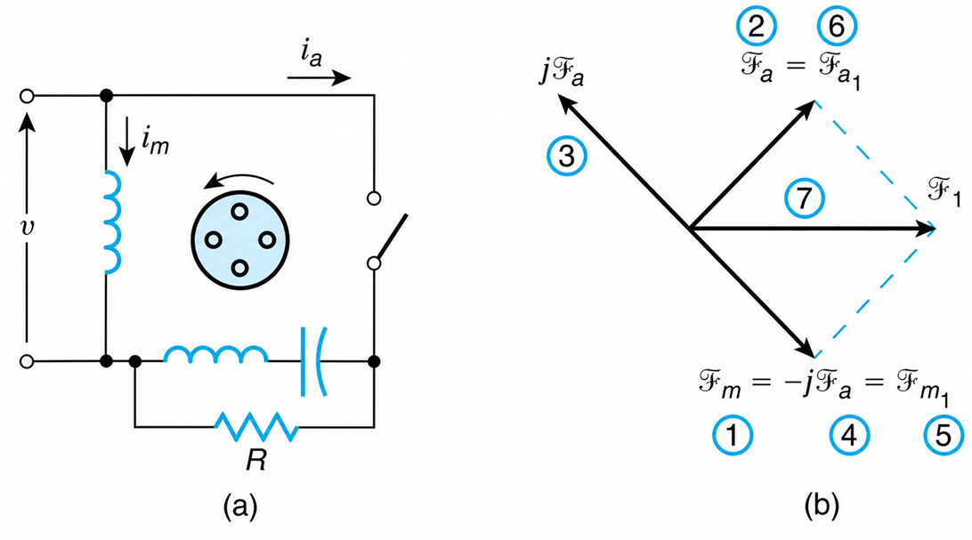
Figure 4-5 Single-phase motor: (a) auxiliary winding with starting capacitor, (b) phasor diagram—ideal case.
Phasor Diagram
Figure 4-5(b) shows the phasor diagram of a capacitor-start motor in an ideal case. Here, the mmf’s are arbitrarily assumed to be equal in magnitude and in space quadrature to each other.
Auxiliary Winding, Removed after Starting
Figure 4-6(a) presents a split-phase induction motor with an auxiliary winding that is removed after starting. The majority of motors, such as those used in ventilating fans and clothes washers/dryers, are of this type. The auxiliary winding can be removed through a centrifugal switch or through the switching action of a relay. The auxiliary winding should be connected in parallel to a properly sized resistor that will dissipate the coils’ stored energy following the current interruption. As can be seen in Figure 4-7, the starting and running torques of this motor are smaller than those of a motor with a permanently connected auxiliary winding that includes a capacitor.
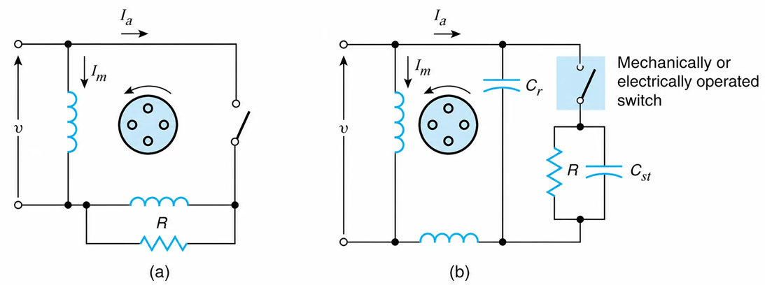
Figure 4-6 Single-phase motor: (a) auxiliary winding, removed after starting, (b) with starting and running capacitors.
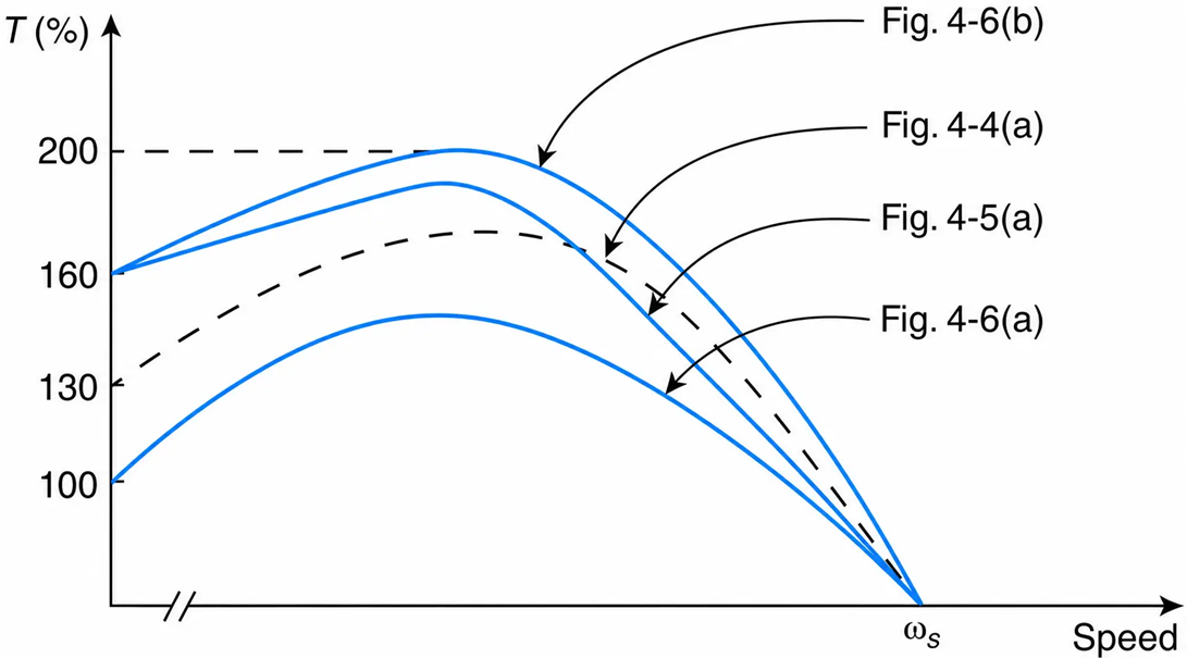
Figure 4-7 Torque-speed characteristic of split-phase induction motors.
Auxiliary Winding, with a Starting and a Running Capacitor
The highest starting and running torque of a single-phase induction motor is obtained when its split-phase winding is equipped, as shown in Figure 4-6(b), with a starting and a running capacitor. For a 3-kW compressor motor, typical values for a starting and a running capacitor are, respectively, $200\ \mu\text{F}$ and $50\ \mu\text{F}$.
Magnetic Fields at Starting
As mentioned previously, at standstill, the currents through the main and auxiliary windings produce two magnetic fields that rotate synchronously in opposite directions. Designating the mmf’s of the main and auxiliary windings $N_mI_m$ and, $N_aI_a$, we have
$$\begin{bmatrix}\mathcal{F}_{m1}\\\mathcal{F}_{m2}\end{bmatrix}=\frac{1}{2}\begin{bmatrix}1&-j\\1&j\end{bmatrix}\begin{bmatrix}N_mI_m\\N_aI_a\end{bmatrix} \ \ \ \ \ (4.13)$$
Where $\mathcal{F}_{m1}$ and $\mathcal{F}_{m1}$ represent, respectively, the positive- and the negative-sequence components of the motor’s mmf, and $I_m$ and $I_1$ are the rms values of the current through the main and auxiliary windings, respectively.
From the matrix equation, we obtain
$$\mathcal{F}_{m1}=\frac{1}{2}\left(N_mI_m-jN_aI_a\right)\ \text{ampere-turns} \ \ \ \ \ (4.14)$$
and
$$\mathcal{F}_{m2}=\frac{1}{2}\left(N_mI_m+jN_aI_a\right)\ \text{ampere-turns} \ \ \ \ \ (4.14)$$
From Equation (4.15), the negative field is zero when the following condition is satisfied.
$$N_mI_m=-jN_aI_a \ \ \ \ \ (4.16)$$
Replacing the currents by their corresponding voltage/impedance ratios (see Figure 4-5(a) and assume $R=\infty$), we obtain
$$N_m\frac{V}{R_m+jX_m}=-jN_a\frac{V}{R_a+jX} \ \ \ \ \ (4.17)$$
where V is the supply voltage and X is equal to the reactance of the auxiliary winding minus the reactance of the capacitor $X_c$. That is,
$$X=X_a-X_c \ \ \ \ \ (4.18)$$
From Equation (4.17), we have
$$N_mR_a+jN_mX=N_aX_m-jN_aR_m \ \ \ \ \ (4.19)$$
Equating the real parts, we obtain
$$R_a=\frac{N_a}{N_m}X_m \ \ \ \ \ (4.20)$$
Equating the imaginary parts, we obtain
$$X=-\frac{N_a}{N_m}R_m \ \ \ \ \ (4.21)$$
Or
$$X_a-X_c=\frac{N_a}{N_m}R_m \ \ \ \ \ (4.22)$$
From the above,
$$X_c=\frac{N_a}{N_m}R_m+X_a \ \ \ \ \ (4.23)$$
Equations (4.20) and (4.23) can be used to design the stator and rotor windings in a way that optimizes the starting torque of the motor. In other words, when these equations are satisfied, a single rotating field is developed at starting.
Example 4-2
A 120 V, 60 Hz, single-phase induction motor of the capacitor-start type has a main winding with 180 effective turns and an auxiliary starting winding with 250 effective turns. With the rotor stationary, the input impedance of the main winding is 5 + j10 ohms and that of the auxiliary winding is 13.89 + j15.50 ohms. Determine at standstill:
a. The magnitude of the forward- and backward-rotating fields.
b. The size of the starting capacitor necessary to yield a single rotating magnetic field at starting.
Solution
a. A schematic of the single-phase induction motor is shown in Figure 4-8. The forward- and backward-rotating magnetic fields of the main winding are obtained from Equations (4.14) and (4.15), respectively.
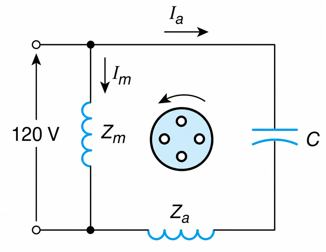
Figure 4-8 Single-phase Induction Motor of the capacitor-Start Type
$$\mathcal{F}_{m1}=\frac{1}{2}\left(N_mI_m-jN_aI_a\right)$$
$$=\frac{1}{2}(120)\left(\frac{180}{5+j10}-j\frac{250}{13.89+j15.50}\right)$$
$$=1349.10\angle-94.5^\circ\ \text{A rms}$$
$$\mathcal{F}_{m2}=\frac{1}{2}\left(N_mI_m+jN_aI_a\right)$$
$$=\frac{1}{2}(120)\left(\frac{180}{5+j10}+j\frac{250}{13.89+j15.50}\right)$$
$$=1041.7\angle-21.6^\circ\ \text{A rms}$$
The positive-sequence component of the auxiliary winding’s mmf is
$$\mathcal{F}_{a1}=j\mathcal{F}_{m1}=1349.10\angle-4.5^\circ\ \text{A rms}$$
and the negative-sequence component is
$$\mathcal{F}_{a2}=-j\mathcal{F}_{m2}=1041.7\angle-111.6^\circ\ \text{A rms}$$
Thus, the net forward-rotating field is
$$\mathcal{F}_1=\mathcal{F}_{a1}+j\mathcal{F}_{m1}=1,349.1\left(1\angle-4.5^\circ+1\angle-4.5^\circ\right)$$
$$=2,698.2\angle-4.5^\circ\ \text{A rms}$$
The net backward-rotating field is
$$\mathcal{F}_2=\mathcal{F}_{a2}+j\mathcal{F}_{m2}=1041.7\left(1\angle-111.6^\circ+1\angle-21.6^\circ\right)$$
$$=90.9\angle155.9^\circ\ \text{A rms}$$
b. To have a single rotating field, the backward-rotating mmf must be equal to zero. That is,
$$\frac{1}{2}(120)\left(\frac{180}{5+j10}+j\frac{250}{Z_a}\right)=0$$
The impedance of the auxiliary winding is
$$Z_a=13.89+j(15.5-X_c)$$
where $X_c$ is the reactance of the capacitor. From the last two relationships,
$$Z_a=-j\left(\frac{250(5+j10)}{180}\right)=13.89+j(15.5-X_c)$$
Solving for $X_c$, we obtain
$$X_c=22.44\ \Omega$$
Thus,
$$C=\frac{1}{\omega X_c}=\frac{1}{2\pi(60)(22.44)}=118.2\ \mu\text{F}$$
Alternatively, using Equation (4.23),
$$X_c=X_a+\frac{N_a}{N_m}R_m=15.5+\frac{250}{180}(5)=22.44\ \Omega$$
This reactance will give the same capacitance as that obtained previously.
