Types of Single-Phase Motors
Split-Phase Motors
The currents in the two stator windings of a split-phase motor are displaced from each other phasewise by either
- making the resistance of one winding higher than that of the other, or
- connecting a capacitor in series with one of the windings.
The resulting magnetic field may be resolved into two oppositely revolving components, one larger than the other, thereby producing a net forward torque.
To avoid overheating, the higher-resistance winding of the split-phase motor, or the winding with the capacitor in a capacitor-start motor, is disconnected when running speed is approached by either a relay’s contact or a centrifugal switch. Once the rotor is turning, excitation of a single stator winding will yield forward torque.
In the same class, with regard to operation while running, is the hand-started induction motor. This motor has only a single stator winding, but it will run in whichever direction it is started.
Shaded-Pole Motors
A shaded-pole, single-phase induction motor has a squirrel-cage rotor and a salient-pole stator (see Figure 4-9). Wound on the stator are the main multi-turn winding and the auxiliary single-turn winding. (Note that this differs from the distributed windings of split-phase motors.) The auxiliary winding is a short-circuited copper band commonly referred to as a shaded-pole winding.
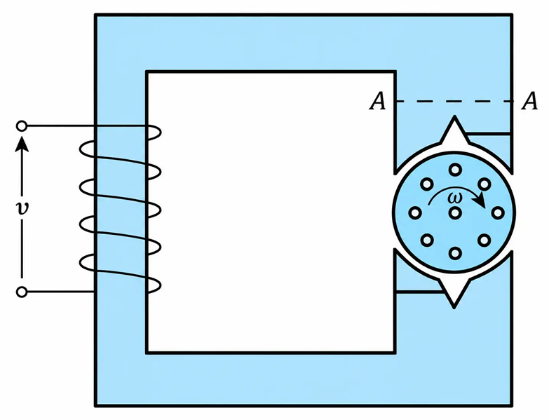
Figure 4.9 Shaded Pole Motor Circuit Diagram
When the main winding is connected to the voltage supply, the flux through the shaded part of the pole lags the flux through the unshaded part because of the opposition to the flux generated by the induced currents in the auxiliary winding. As a result, the stator flux has two components, one of which lags the other. Each of these fluxes completes its loop through the stator poles, air gaps, and rotor.
Revolving Field
The flux through the stator at section A-A $(\phi_A)$ is the vector sum of the fluxes through the shaded $(\phi_{sh})$ and unshaded $(\phi_{un})$ parts of the pole. Thus,
$$\phi_A=\phi_{un}+\phi_{sh} \ \ \ \ \ (4.24)$$
Or
$$\phi_A=\phi_{un}\left(1\angle0^\circ+K\angle-\theta\right) \ \ \ \ \ (4.25)$$
where: $K=\frac{\phi_{sh}}{\phi_{un}}$ and $\theta$ is the phase angle by which the flux through the shaded part of the pole lags the flux through the unshaded part of the pole.
The parameters $\phi_{un}$, K, and $\theta$ are variables, and, at a particular point in the voltage waveform, have a unique value. As a result, the stator flux has two rectangular components that change as a function of time, which leads to the development of a kind of spacewise revolving field.
The rotor is subjected to two magnetizing forces whose vector sum induces a rotor current and a corresponding rotor flux. The interaction of stator and rotor fluxes produces torque and rotation whose direction is from the unshaded to the shaded part of the pole.
Shaded-pole motors have a low power factor (0.25 to 0.50) and efficiency (0.25 to 0.40), but are very economical to manufacture. Their power rating is in the range of 1 mW to 200 W. Almost all motors rated at less than 50 W are of the shaded-pole type. Their starting torque is 0.30 to 0.85 pu, and their maximum torque is 1.2 to 1.5 pu.
Usually, shaded motors have two, four, or six poles. When supplied with integral gear systems, they can drive loads at speeds that are slower than one revolution per day. Shaded-pole motors are used in photocopy machines, humidifiers, fans, toys, phonograph turntables, and many other products.
Stepper Motors
Stepper motors rotate in increments or steps that are determined by rotor construction and the type of stator excitation. The stator winding is often a multiphase winding (sometimes up to four phases are used), and the excitation voltage is a series of current pulses (digital signal). The higher the number of stator phases, the smaller the increment of angular rotation per input pulse.
The rotor may be one of two types: permanent magnet or reluctance. A four-pole reluctance motor is shown in Figure 4-10(a). The shaft of this kind of motor has one salient rotor configuration for each stator phase. That is, for a four-phase stator winding, the rotor will have along its axis four distinct pole configurations. When one of the stator windings is excited, the rotor will rotate in such a way that the path of least reluctance is established for the stator flux.
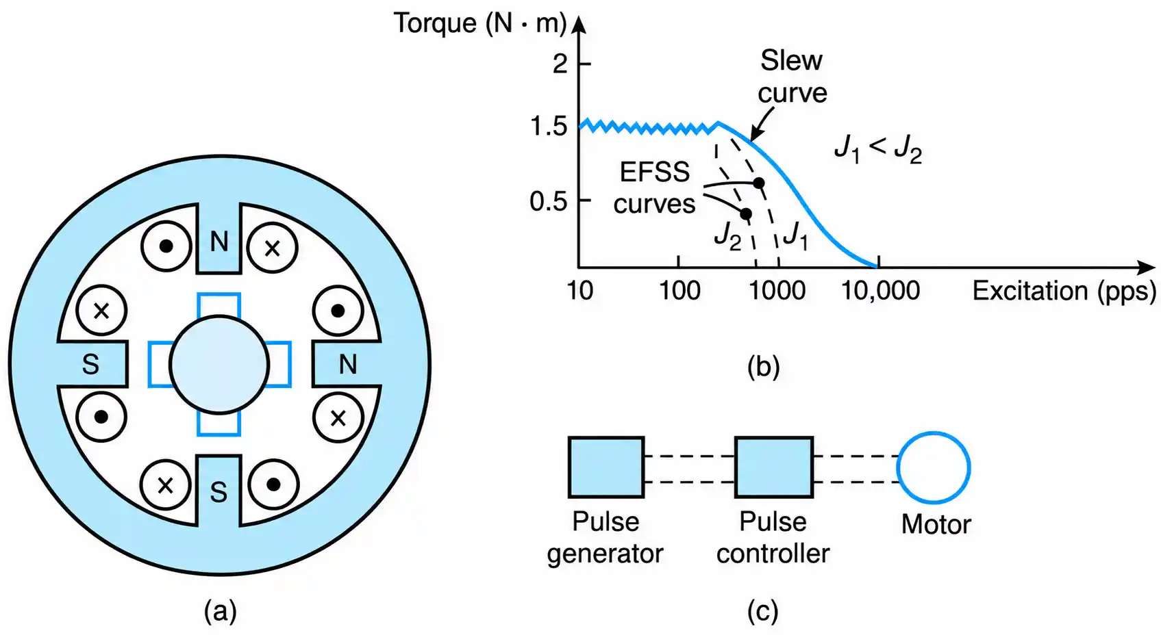
Figure 4-10 Stepper motors: (a) a four-pole reluctance motor, (b) torque: excitation characteristics, and (c) control configuration.
Reluctance motors can operate with a minimum rotation of $1.8^\circ/\text{pulse}$; that is, to effect a complete revolution, 200 pulses are required. The characteristics of stepper motors [see Figure 4-10(b)] are expressed in terms of the torque produced as a function of excitation pulses per second (pps).
The torque of the motor is constant up to a specific rate of excitation pulses. At a further increase in the rate of excitation pulses, the torque is decreased either along the solid curve or along the dotted line characteristic.
In Figure 4-10(b):
- The dotted lines represent the motor operation without controlled acceleration and deceleration. This operation is referred to as an error-free-start-stop (EFSS) operation. In this mode of operation, the higher the effective moment of inertia, the lower the motor’s output torque.
- The solid line characteristic represents a motor operation with controlled acceleration and deceleration. The solid line characteristic is commonly known as the slew curve.
Permanent magnet stepping motors develop higher torque than reluctance motors and rotate in larger steps per unit pulse excitation.
Control
Since the position of the rotor in a stepper motor depends on the number of pulses it receives, one can easily control the rotation of the shaft by controlling the number of pulses.
Figure 4-10(c) shows the control configuration of a stepper motor. It is an open-loop control where the generated pulses are applied to the motor’s windings at a controlled rate through a programmable digital controller. The characteristics of a simple open-loop control system are compatible to those of the closed-loop design.
Stepper motors at steady state accelerate and decelerate with each pulse and consequently are not useful for applications that require smooth steady-state speed, such as phonograph drives. Stepper motors are employed in the positioning of machine tools, computer disk drives, printers, typewriters, sewing machines, and others.
Series AC/DC Motors
Small single-phase motors that can operate with either dc or ac input voltage are called universal or series ac/dc motors. These motors are normally rated at less than 1 kW, and their speed is usually between 2000 and 12,000 r/min. They are generally used in hand tools and household appliances. They operate much like dc series motors.
The equivalent circuit of series ac/dc motors and its torque-speed characteristics are shown in Figures 4-11(a) and (b), respectively. The field current $\left(I_f\right)$ is equal to the armature current $\left(I_a\right)$ because the field and armature are connected in series. The voltage generated in the armature winding, $\left(V_g\right)$, is given by
$$V_g=K\phi\omega \ \ \ \ \ (4.26)$$
where K is a constant of the motor and $\phi$ is its effective field. The torque developed by the motor is proportional to the effective flux and to the current drawn from the line. Mathematically,
$$T=K\phi I_a \ \ \ \ \ (4.27)$$
The constant of proportionality is given by the following Equation.
$$K=\frac{Np}{\beta\pi}$$
Where
$N=\text{turns of armature winding}$
$p=\text{number of poles}$
$\beta=\text{number of parallel paths of the armature winding}$
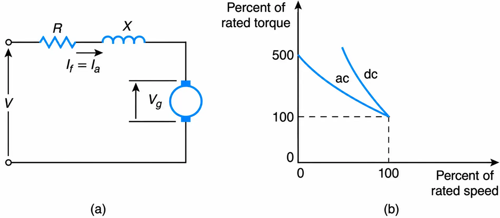
Figure 4-11 Universal motor: (a) equivalent circuit, (b) typical torque-speed characteristics.
At a specified speed, the motor develops less torque for an ac operation than it does for a dc operation. This situation is due to magnetic losses and to the fact that, for ac operations, the armature current is reduced because of the inductive reactance of the motor’s winding.
