Magnetic Flux
Magnetic flux is a characteristic of magnetic fields, just as electric flux is a characteristic of electric fields. Magnetic flux may be thought of as representing the lines of force between a north magnetic pole and a south magnetic pole. Magnetic flux is represented by the Greek letter $\phi$(phi), and in the SI system of units it is measured in, or has the unit of, webers (Wb).
Refer to Figure 1-45. The magnetic flux emerges from the north magnetic pole, goes through the south pole, and returns again to the north pole. In other words, the magnetic flux or the magnetic lines of force are continuous, and thus they form a “closed loop.” This flux always exists between the poles of a magnet and will arrange itself to conform to the shape of any magnet.
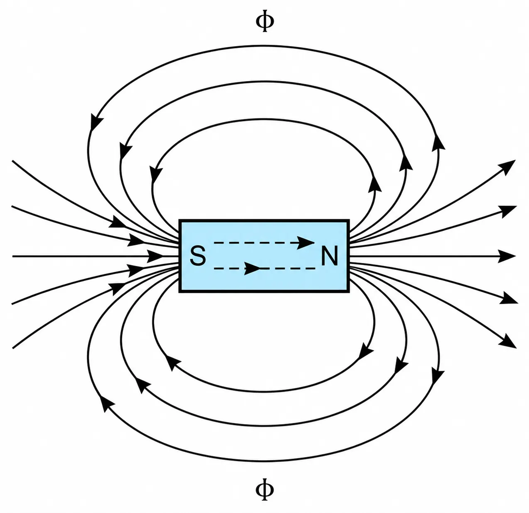
Figure 1-45 A magnet and its magnetic flux.
Figure 1-46 shows the tracing of magnetic fields by means of iron fillings.
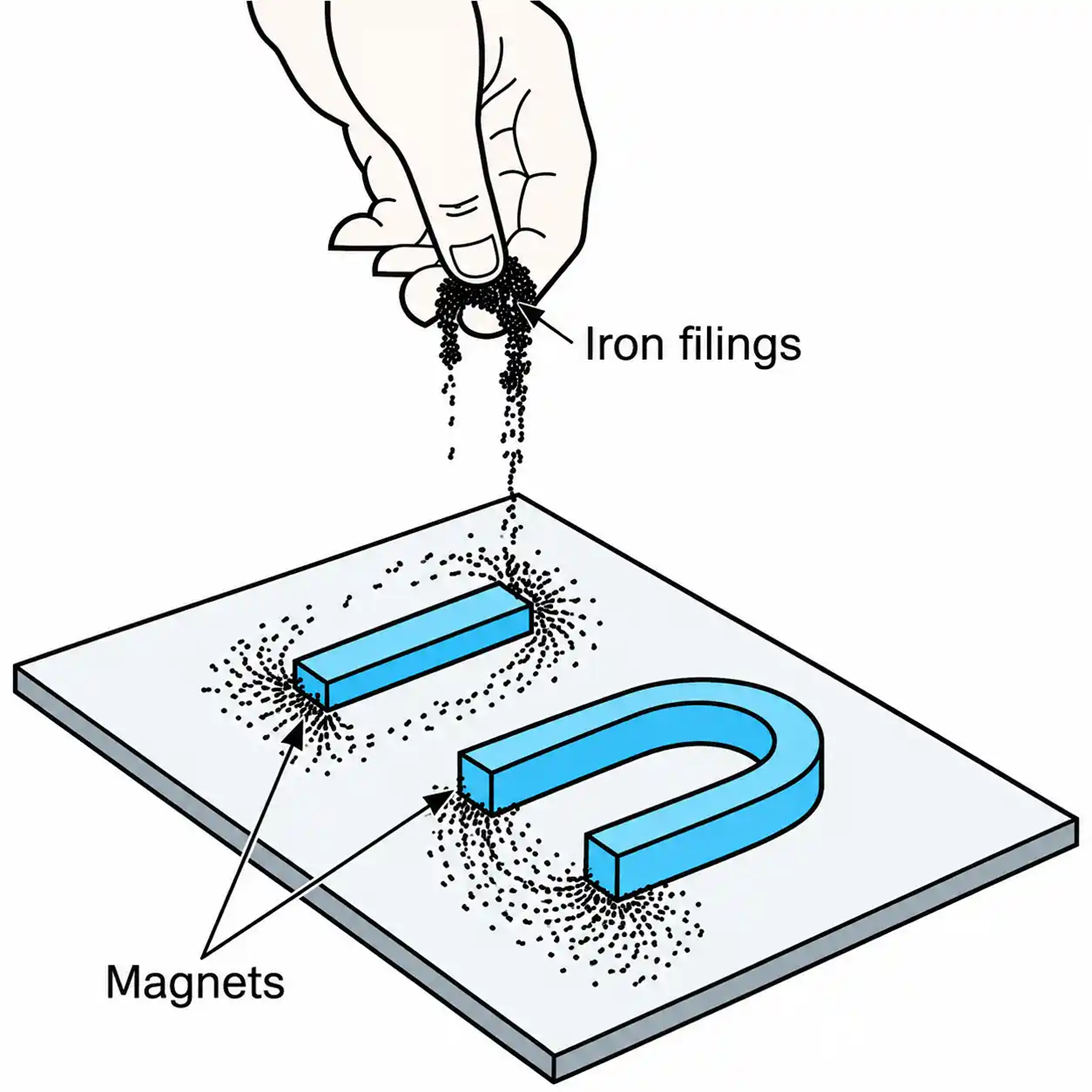
Figure 1-46 Tracing the magnetic fields by means of iron filings.
Figure 1-47 shows an illustration of earth’s magnetic field. The magnetic field intensity of the earth’s field is about 0.31 A/m (0.0038 Gauss) at the equator and 0.7 A/m (0.009 Gauss) at the poles. The purpose of these approximate values is to provide a basis for comparing the strength of magnetic fields.
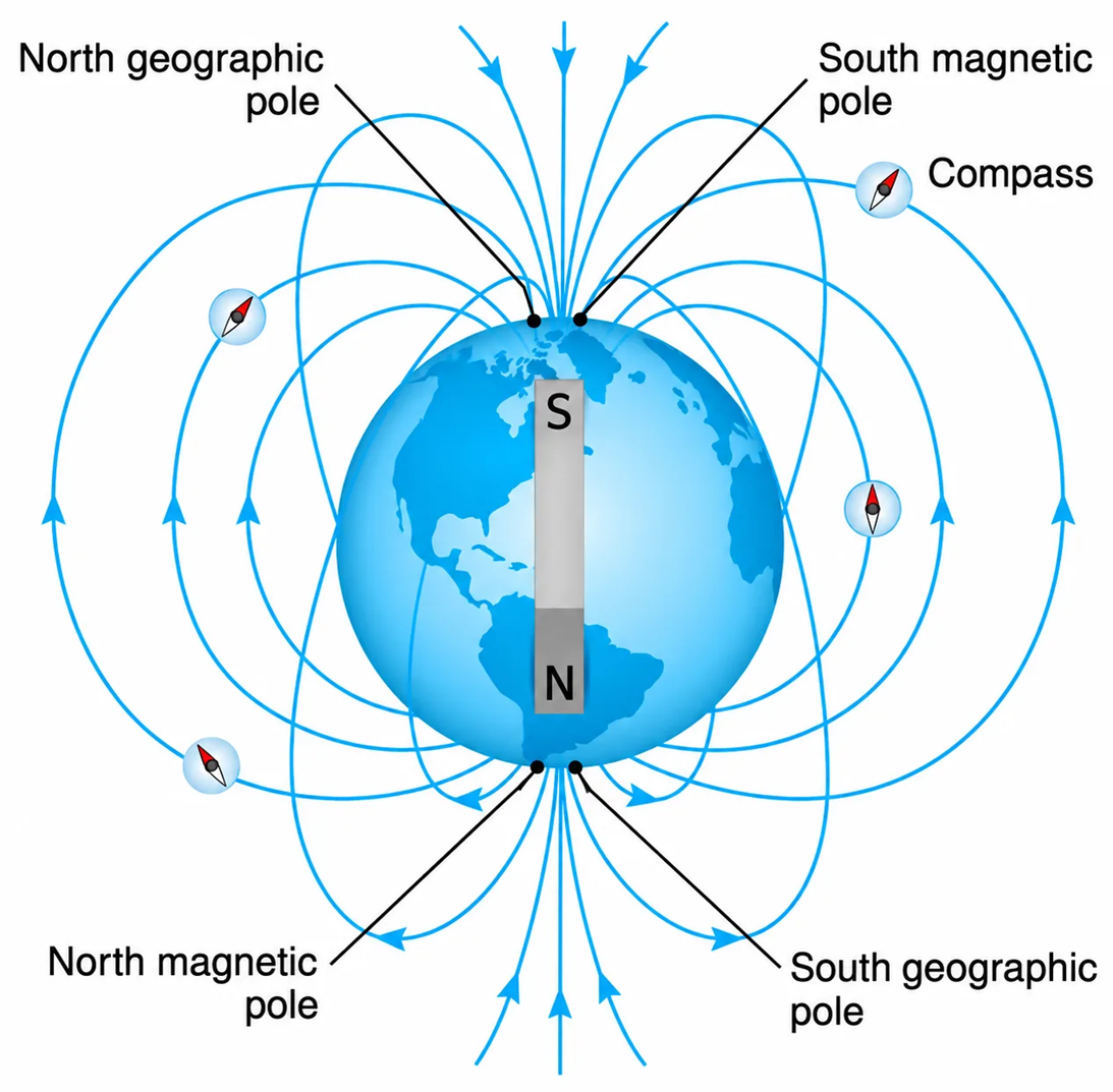
Figure 1-47 Illustration of Earth’s magnetic field. The geomagnetic field of the Earth is very similar to that of a large bar magnet placed at the center of the Earth, with its south end oriented toward the north magnetic pole.
The flux produced by a coil wound around a magnetic material depends on the properties of the
- magnetic material,
- number of turns in the winding, and
- current through the winding
It has been verified that the migration of birds and fish is controlled by the orientation of their internal tiny magnets relative to that of the Earth’s magnetic field and the rotation of its north–south geographical axis.
Figure 1-48 depicts two coils and their corresponding flux lines.
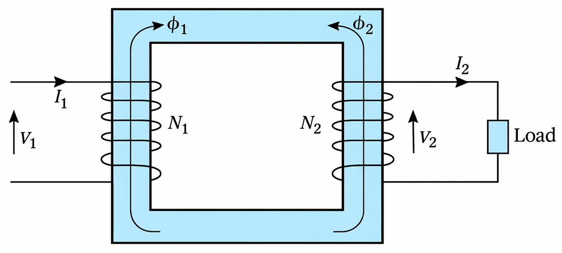
Figure 1-48 Interaction of magnetic fields.
Since the current through a winding depends on the applied voltage, the flux can also be expressed as a function of the applied voltage.
The direction of magnetic flux is obtained by using the so-called right-hand rule. According to this rule (see Figure 1-49), when a conductor is held with the right hand and the thumb is pointing in the direction of current flow, then the other fingers curl in the direction of flux.
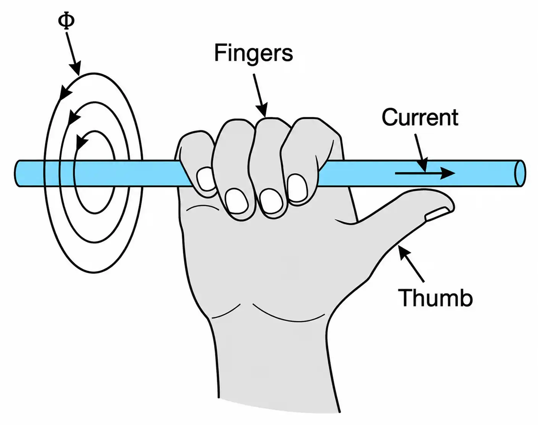
Figure 1-49 Illustration of the right-hand rule.
Consider coil 1, shown in Figure 1-50. The flux generated by the coil’s current has two components. Component $\phi_{12}$ links both coils; component $\phi_{11}$ links only coil 1. $\phi_{12}$ and $\phi_{11}$ are called the mutual and leakage flux, respectively. Thus, the total flux $\phi_{1}$ generated by coil 1 is
$$\phi_1=\phi_{11}+\phi_{12} \ \ \ \ \ (1.99)$$
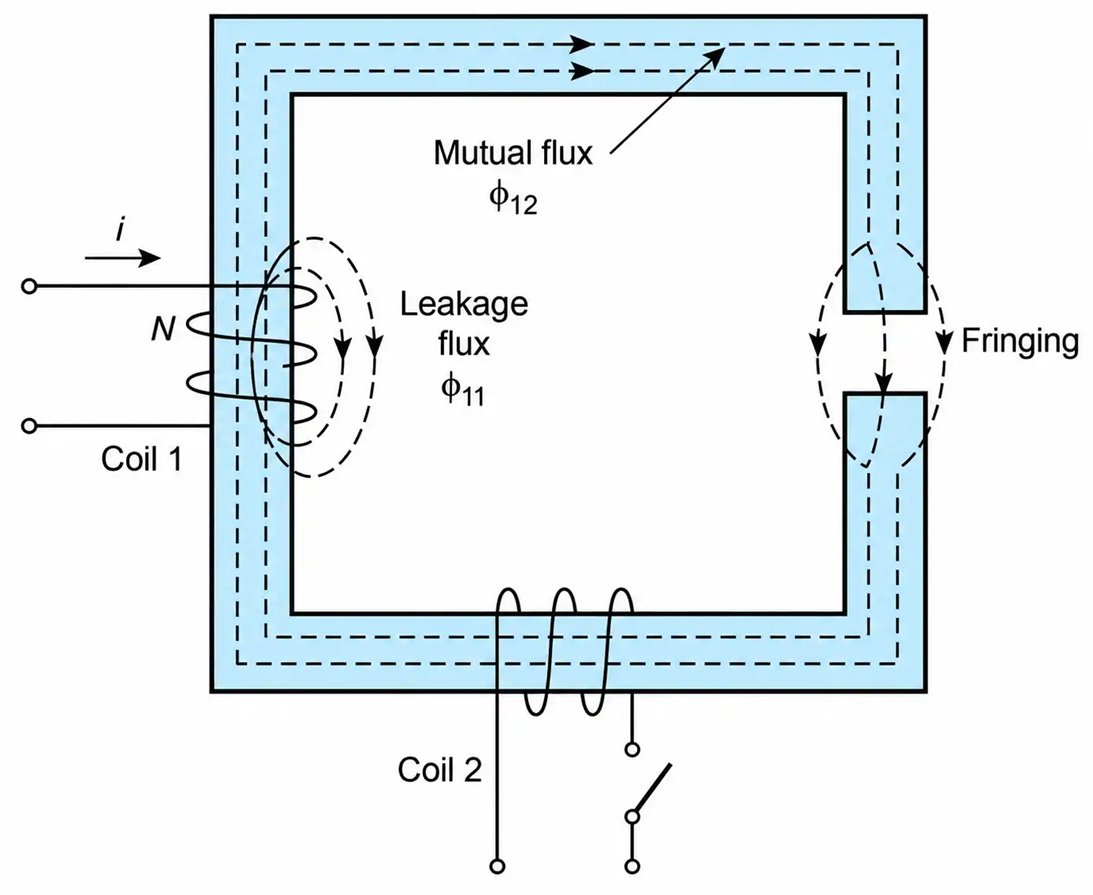
Figure 1-50 An illustration of the concept of mutual flux, leakage flux, and fringing.
The spreading out of the mutual flux around the air gap is called fringing.
The product of the winding turns and the flux that links them is called the flux linkage. Flux linkage is generally represented by the Greek letter $\lambda$ (lambda). Thus,
$$\lambda_{11}=N\phi_{11} \ \ \ \ \ (1.100)$$
$$\lambda_{12}=N\phi_{12} \ \ \ \ \ (1.101)$$
where $\lambda_{11}$ and $\lambda_{12}$ are the leakage and mutual flux linkages of winding 1, respectively.
The total flux linkage $\lambda_{1}$ of coil 1 is then
$$\lambda_1=\lambda_{11}+\lambda_{12} \ \ \ \ \ (1.102)$$
The concept of flux linkage constitutes the basis for deriving general expressions for the inductance and voltage induced in a coil.
Example 1-17
The total flux produced by the 100-turn coil in Figure 1-51 is 0.005 Wb.
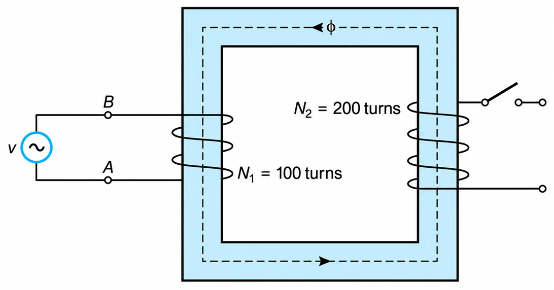
Figure 1-51 Magnetic Flux produced by the 100-turn Coil
Assuming that the leakage flux is 4% of the total flux, determine:
a. The flux linkage of each winding.
b. The relative polarity of the voltage source.
Solution
a. Designating with $\lambda_{1}$ and $\lambda_{2}$ the flux linkage of coil 1 and coil 2, we have
$$\lambda_1=N_1(\phi_{11}+\phi_{12})$$
$$\lambda_2=N_2\phi_{12}$$
Where $\phi_{11}$ is the flux that links only coil 1, and $\phi_{12}$ is the flux that links both coils. Substituting the given values, we obtain
$$\lambda_1=100(0.005)=0.5\ \text{Wb}$$
And
$$\lambda_2=200(0.005)\left(1-\frac{4}{100}\right)=0.96\ \text{Wb}$$
b. The relative polarity of the voltage supply controls the direction of the current flow, which in turn controls the direction of the flux flow. Using the right-hand rule, we see that the current must flow from terminal A to terminal B in a counterclockwise direction. Thus, the potential of point A is higher than the potential of point B.
