Understanding the Per-Unit System
When engineering parameters such as power, torque, speed, voltage, current, and impedance are expressed in their corresponding per-unit values, many engineering concepts and calculations are simplified. For this reason, almost all design and problem solving in the power-distribution field is implemented by expressing all pertinent parameters in their equivalent per-unit values.
Actual engineering parameters are changed to their equivalent per-unit values as follows. The per-unit value of a parameter K is equal to its actual value divided by the base value. That is,
$$K=\frac{\text{actual value of }K}{\text{base value of }K}\ \text{pu} \ \ \ \ \ (2.40)$$
Base parameters are normally obtained from the nameplate data of the transformer, as follows:
$$S_b=\text{volt-ampere rating of the transformer} \ \ \ \ \ (2.40a)$$
$$V_b=\text{rated voltage of the winding under consideration} \ \ \ \ \ (2.40b)$$
$$I_b=\frac{S_b}{V_b} \ \ \ \ \ (2.40c)$$
$$Z_b=\frac{\text{base value of voltage}}{\text{base value of current}} \ \ \ \ \ (2.40d)$$
From Equations (2.40c) and (2.40d), we obtain
$$Z_b=\frac{V_b^2}{S_b} \ \ \ \ \ (2.41)$$
The base power is the same in both the high- and the low-voltage windings (SbH = SbL). In contrast, the base voltage, base current, and base impedance are different for each winding of the transformer, and thus the subscript H or L should be included in the above expressions to represent parameters at the high-and low-voltage windings. The base value is the value of the parameter expressed in standard engineering units.
When the ohmic value of an impedance is $15 \angle 40^\circ$ ohms and the value of the base impedance is 300 ohms, then the per-unit value of the impedance is
$$Z=\frac{15\angle40^\circ}{300}=0.05\angle40^\circ\ \text{pu}$$
Similarly, when the actual value of a voltage is 250 volts, and the base voltage is 200 volts, then the per-unit value of the voltage is
$$V = \frac{250}{200} = 1.25\ \text{pu}$$
The per-unit value of a parameter, multiplied by 100, gives the value of the parameter in percent. Thus, when the per-unit value of a parameter is 0.04, its percentage value is 4%.
One advantage of the per-unit system is that when the voltage, current, and impedance of a transformer are expressed in per-unit, they have the same values regardless of the side of the transformer to which they refer. This greatly simplifies the understanding and solution of various transformer problems.
An additional advantage is that when the parameters of a machine are expressed as per-unit, they all fall within a known range, regardless of the rating of the machine. The per-unit values of the equivalent leakage impedance of most single-phase transformers, for example, are within the range of 0.035–0.055 pu. Knowing this is of tremendous importance, greatly simplifying the solution of problems and the conceptual understanding of various transformer operating conditions.
It can be shown that the per-unit value of the transformer’s leakage impedance is equal to the voltage required on a short-circuit test, expressed as per-unit of the rated value. That is,
$$Z_{e,\text{pu}}=V_{z,\text{pu}} \ \ \ \ \ (2.42)$$
One-Line Diagrams
Transformers, cables, and electric machines are conventionally identified in electrical drawings by their equivalent one-line representations. As the name implies, one-line diagrams represent electrical loads as being supplied through one wire, regardless of how many wires are used in the actual setup.
The main parameters of a system—per-unit impedances, kVA rating of transformers, kW rating of motors, size of cables, protective devices, the short-circuit MVA of the supply voltage source, and so on—are written on one-line diagrams.
For a single-phase system, the short-circuit apparent power $\left| S \right|$ in volt-amperes is
$$|S|=VI_{sc} \ \ \ \ \ (2.43)$$
where V and Isc are, respectively, the nominal voltage and the short-circuit current. When the voltage is expressed in kV and the short-circuit current in kA, then Equation (2.43) gives the short circuit apparent power in MVA.
From Equation (2.43) and Ohm’s law, we obtain
$$|S|=V\frac{V}{Z} \ \ \ \ \ (2.44)$$
where Z is the impedance of the supply network in ohms/phase. From Equations (2.43) and (2.44), we obtain
$$Z=\frac{V^2}{|S|} \ \ \ \ \ (2.45)$$
For a three-phase system, the short-circuit MVA is
$$S=\sqrt{3}\,V_{L\!-\!L}\,I_{sc} \ \ \ \ \ (2.46)$$
where VL-L and ISC are, respectively, the line-to-line nominal voltage expressed in kV and the short-circuit current expressed in kA. Thus, the short-circuit MVA of a given voltage source can be used to find the internal impedance of the source and/or the short-circuit current.
Protective equipment, such as circuit breakers and fuses, must be capable of safely withstanding the forces produced by the short-circuit currents. Since the short-circuit currents are given indirectly in terms of short-circuit MVA, it is customary in the industry to rate the short-circuit capacity of equipment in terms of short-circuit MVA.
Typical short-circuit MVA’s for a 25 kV and 46 kV distribution system are as follows:
|
kV |
MVA |
|
25 |
500 |
|
46 |
1500 |
Under ideal conditions, the source impedance is equal to zero and its frequency is constant. Such a system is identified on the one-line diagram as an “infinite bus.”
In more general terms an infinite bus is a power source whose voltage and frequency remain constant independent of the active or reactive power being supplied.
Since electrical power systems are commonly represented using one-line diagrams, the one-line diagram is used throughout this article wherever applicable. Figure 2-21(a) shows a two-wire diagram of a single-phase load. The 120 V, 60 Hz voltage supply has an internal reactance of 0.1 ohm. The 15 A fuses protect the 1.2 kW load from undesirable high currents. The two-conductor (2c) cable is size #12 AWG (American Wire Gauge). When the load is shorted, the resulting short-circuit MVA is
$$|S| = V|I|$$
$$|S| = 120\left(\frac{120}{0.1}\right)\times 10^{-6}$$
$$= 0.144\ \text{MVA}$$
The one-line diagram of Figure. 2-21(a) is shown in Figure. 2-21(b).
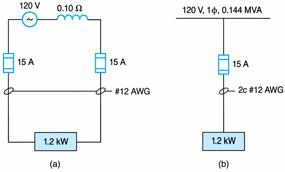
Figure 2-21 Representation of a distribution system. (a) Two-wire. (b) One-line
Example 2-3
A 5 kVA, 480–120 V single-phase transformer delivers rated current at 0.9 pf lagging. The transformer’s equivalent leakage impedance referred to the high-voltage winding is 0.92 + j1.84 ohms. Find the per-unit values of the voltage, current, and leakage impedance on the HV and LV winding.
Solution
The approximate equivalent circuit of the transformer is shown in Figure. 2-22.
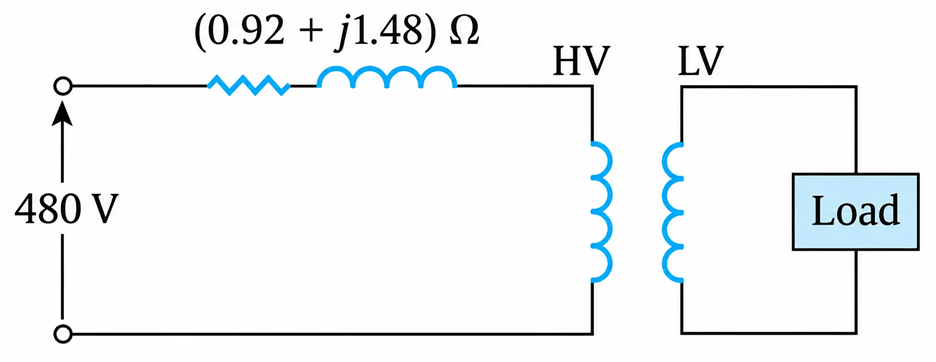
Figure 2-22 Transformer’s equivalent leakage impedance referred to the high-voltage winding
HV Side
The base parameters are
$$S_b = 5000\ \text{VA}$$
$$V_{bH} = 480\ \text{V}$$
$$I_{bH} = \frac{5000}{480} = 10.42\ \text{A}$$
$$Z_{bH} = \frac{(480)^2}{5000} = 46.08\ \text{ohms}$$
The per-unit values are
$$V_H = \frac{\text{actual value}}{\text{base value}} = \frac{480}{480} = 1.0\ \text{pu}$$
$$I_H = \frac{10.42 \angle -25.8^\circ}{10.42} = 1.0 \angle -25.8^\circ\ \text{pu}$$
$$Z_H = \frac{0.92 + j1.84}{46.08} = 0.02 + j0.04\ \text{pu}$$
LV Side
The base parameters are
$$S_b = 5000\ \text{VA}$$
$$V_{bL} = 120\ \text{V}$$
$$I_{bL} = \frac{5000}{120} = 41.67\ \text{A}$$
$$Z_{bL} = \frac{(120)^2}{5000} = 2.88\ \text{ohms}$$
The per-unit values are
$$V_L = \frac{120}{120} = 1.0\ \text{pu}$$
$$I_L = \frac{41.67 \angle -25.8^\circ}{41.67} = 1.0 \angle -25.8^\circ\ \text{pu}$$
The leakage impedance referred to the LV side is
$$Z_e = (0.92 + j1.84)\left(\frac{120}{480}\right)^2 = 0.06 + j0.12\ \Omega$$
$$Z_e = \frac{0.06 + j0.12}{2.88} = 0.02 + j0.04\ \text{pu}$$
Example 2-4
The 100 kVA, 440–220 V, 60 Hz single-phase transformer shown in the one-line diagram representation (Figure. 2-23(a)) has negligible magnetizing current and a leakage impedance of 0.03 + j0.040 pu. The transformer is connected to a 440 V source through a feeder whose impedance is 0.04 + j0.08 ohms.
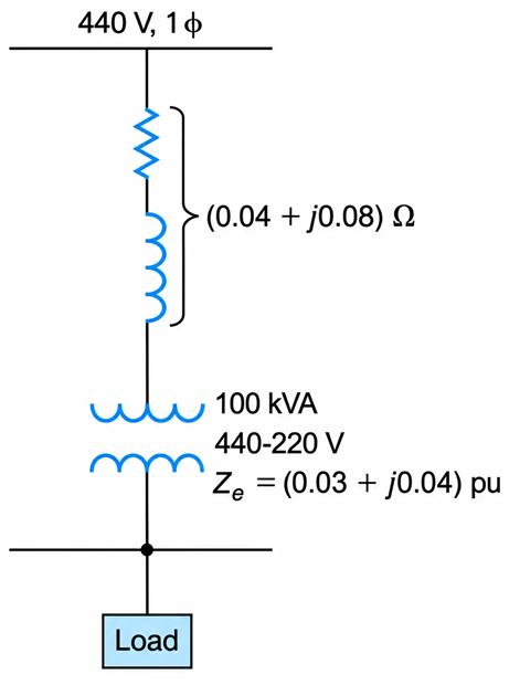
Figure 2-23(a) Transformer and Feeder Single-Line Diagram
Determine:
a. The voltage across the load when the transformer is connected to a 440 V source and delivers rated current to a load of 0.80 power factor lagging.
b. The voltage regulation.
c. The primary and secondary short-circuit MVA when the secondary of the transformer is shorted.
d. The rating of the capacitor in kVAR which, when connected across the load, will improve the power factor from 0.80 lagging to unity.
Solution
a. The base impedance in the HV winding is
$$Z_{bH} = \frac{(440)^2}{100{,}000} = 1.94\ \Omega$$
The per-unit value of the voltage is
$$V_{\text{pu}} = \frac{\text{actual value}}{\text{base value}} = \frac{440}{440} = 1.0\ \text{pu}$$
Similarly,
$$I_{\text{pu}} = 1.0 \angle -36.9^\circ\ \text{pu}$$
The per-unit value of the feeder impedance is
$$Z_f = \frac{\text{actual value}}{\text{base value}}$$
$$Z_f = \frac{0.04 + j0.08}{1.94} = 0.02 + j0.04\ \text{pu}$$
Applying KVL to the equivalent circuit of Figure. 2-23(b) and using per-unit values, we have
$$V_L = V_1 - IZ$$
Or
$$V_L\angle0^\circ=1.0\angle\beta_1^\circ-1.0\angle-36.9^\circ\left[0.03+0.02+j(0.04+0.04)\right] \ \ \ \ \ (I)$$
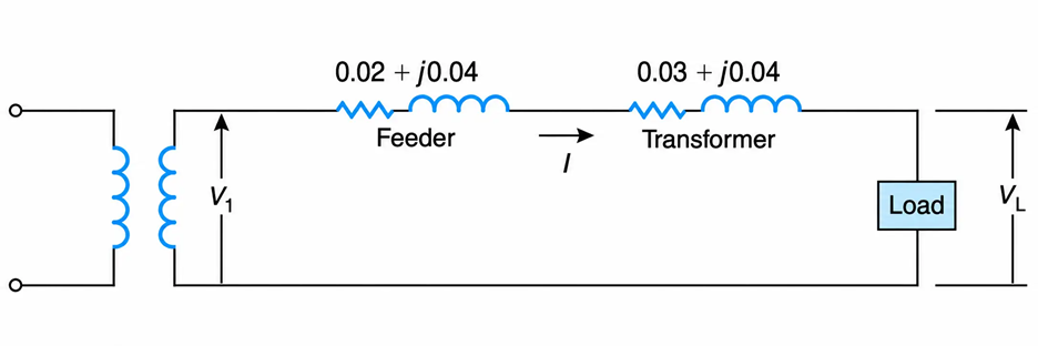
Figure 2-23(b) Equivalent Circuit for Transformer and Feeder
The given power factor of the load establishes the reference for the phase angles.
In other words, the voltage across the load has a phase angle equal to zero, while the input voltage will be at an angle of β1 degrees to the reference.
From Equation (I), and after some algebraic calculations, we obtain
$$V_L \angle 0^\circ = 1.0 \angle \beta_1^\circ - 0.096 \angle 21.2^\circ$$
Equating the imaginary components of the above equation, we get
$$\beta_1 = \arcsin\left(0.096 \sin 21.2^\circ\right) = 2^\circ$$
Equating the real components, we obtain
$$V_L = 1.0\cos 2^\circ - 0.096\cos 21.2^\circ$$
$$V_L = 0.91\ \text{pu}$$
$$V_L = 0.91(220)$$
$$V_L = 200.21\ \text{V}$$
Alternatively, using ohmic values, from KVL we have
$$Z_t = 1.94(0.03 + j0.044) = 0.06 + j0.08\ \Omega$$
The total impedance referred to the HV winding is
$$Z = (0.06 + j0.08) + (0.04 + j0.08) = 0.19 \angle 58^\circ\ \Omega$$
The magnitude of the current in the HV is
$$|I| = \frac{100{,}000}{440}$$
$$|I| = 227.27\ \text{A}$$
Thus,
$$V_L = \frac{1}{2}\left(440 \angle \beta_1^\circ - IZ\right)$$
Or
$$V_L \angle 0^\circ = \frac{1}{2}\left[440 \angle \beta_1^\circ - 227.27 \angle -36.9^\circ (0.19 \angle 58^\circ)\right]$$
$$= \frac{1}{2}\left[440 \angle \beta_1^\circ - 42.156 \angle 21.2^\circ\right]$$
Equating the imaginary components of the last equation, we obtain
$$\beta_1 = \arcsin\left(\frac{15.25}{440}\right) = 2^\circ$$
Equating the real components, we obtain
$$V_L = \frac{1}{2}\left(440 \cos 2^\circ - 39.3\right) = 200.21\ \text{V}$$
b. Using Equation (2.39), the regulation in percent is
$$\text{regulation} \% = \frac{220 - 200.21}{200.21} \times 100 = 9.9\%$$
c. The short-circuit volt-amperes are given by
$$(VA)_{sc} = V_{\text{rated}} I_{sc}$$
$$I_{sc} = \frac{V}{|Z|} = \frac{440}{0.19}$$
$$I_{sc} = 0.2372\ \text{A}$$
The short-circuit VA expressed in MVA is
$$(\text{MVA})_{sc} = 0.440(2.372)$$
$$(\text{MVA})_{sc} = 1.044\ \text{MVA}$$
Owing to the transformation properties of the transformer, the short-circuit MVA is the same whether it is referred to the high- or low-voltage winding. The power triangle and the phasor diagram of the load are shown in Figure. 2-23(c).
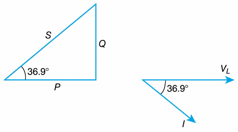
Figure 2-23( c) Power Triangle and the Phasor Diagram of the Load
d. The required reactive power (Qc) of the capacitor is
$$Q_c = P \tan \theta$$
from which
$$Q_c = 100(0.8)\tan 36.9^\circ$$
$$Q_c = 60\ \text{kVAR}$$
