Magnetic Flux Density and Magnetomotive Force
Magnetic Flux Density
Magnetic flux density is defined as the ratio of the magnetic flux divided by the area perpendicular to the flux. In mathematical symbols,
$$B=\frac{\phi}{A} \ \ \ \ \ (1.103)$$
where B is the flux density.
The unit of flux density in the SI system of units is the tesla, abbreviated by the letter T.
Considering incremental changes in the area, from Equation (1.103) we get
$$\phi=\int B\,dA \ \ \ \ \ (1.104)$$
The flux density of a material is a measure of its magnetization, which reveals the magnetic status of the material.
The nominal magnetization level of an apparatus’s magnetic material depends on the design of its magnetic circuit. For example, the flux density of the coils used for communication purposes is maintained at about 0.001 T, while the flux density of power transformers, under normal operating conditions, is about 0.9 T.
The flux density in an air gap can be easily measured by using a Gauss meter. The design of such a meter may be based on the “Hall effect.”
According to this principle, the voltage induced in a probe—usually made from a thin semiconductor material—that carries current (i) perpendicular to the magnetic field density (B) is given by
$$\nu=KiB \ \ \ \ \ (1.105)$$
where K is a constant of proportionality that depends on the physical dimensions of the probe.
When the probe of a Gauss meter that carries a constant current is placed perpendicular to a magnetic field, the induced voltage will be indicated on the scale of the meter. The manufacturer of the meter gives the constants that relate the voltage to the magnetic flux and to the flux density.
Magnetomotive Force
The magnetomotive force (mmf), or the magnetic potential of a coil, is given by the product of the winding’s current (i) times its number of turns (N). That is,
$$\mathrm{mmf}=Ni \ \ \ \ \ (1.106)$$
The mmf is also represented by the following symbols:
$$\mathrm{mmf}=\mathcal{F}=U$$
The unit of the mmf in the SI system of units is ampere-turns (A).
When a coil is connected to an electric voltage, as shown in Figure 1-52, a current will flow, which in turn will produce an mmf.
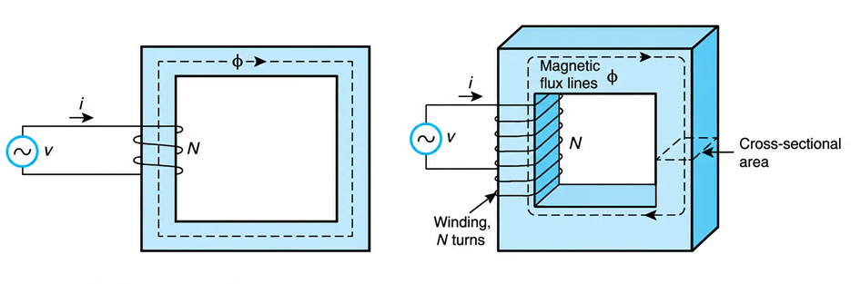
Figure 1-52 Physical representation of a magnetic circuit. (Leakage flux is neglected.)
The mmf, like the current, has an instantaneous, average, and effective value. When the mmf is of sinusoidal waveform, it can be represented by a phasor having the same phase angle as that of the current that produces it.
The mmf may be thought of as the driving force of transformers and electric machines, just as the emf constitutes the driving force in incandescent lamps and electric heaters. The polarity of the mmf is as critical to magnetic circuits as the polarity of the emf is to electric circuits.
Example 1-18
When a sinusoidal voltage source of 60 Hz and 120 V is connected to a 50-turn coil, a current of 15 A rms circulates. Assuming a linear magnetic circuit, determine the maximum value and the instantaneous value of the mmf.
Solution
The maximum value of the current is
$$I_m=\sqrt{2}\,I_{rms}=\sqrt{2}(15)=21.21\ \text{A}$$
By definition, therefore, the maximum value of the coil’s mmf is
$$\mathcal{F}_{\max}=NI_{\max}=50(21.21)=1060.66\ \text{A}$$
Since the current is a sinusoidal function, the mmf will also be a sinusoidal function. Thus,
$$\mathcal{F}=\mathcal{F}_m\sin\omega t=1060.66\sin377t\ \text{A}$$
