Autotransformer Operation and Disadvantages
This section covers the principles of operation, equivalent circuits and losses. Figure 2-45(a) shows the schematic representation of a 10 kVA, 200–100 V, single-phase transformer. Its autotransformer-type connection can be obtained as shown in Figures 2-45(b) and (c), by a special interconnection of its primary and secondary windings.
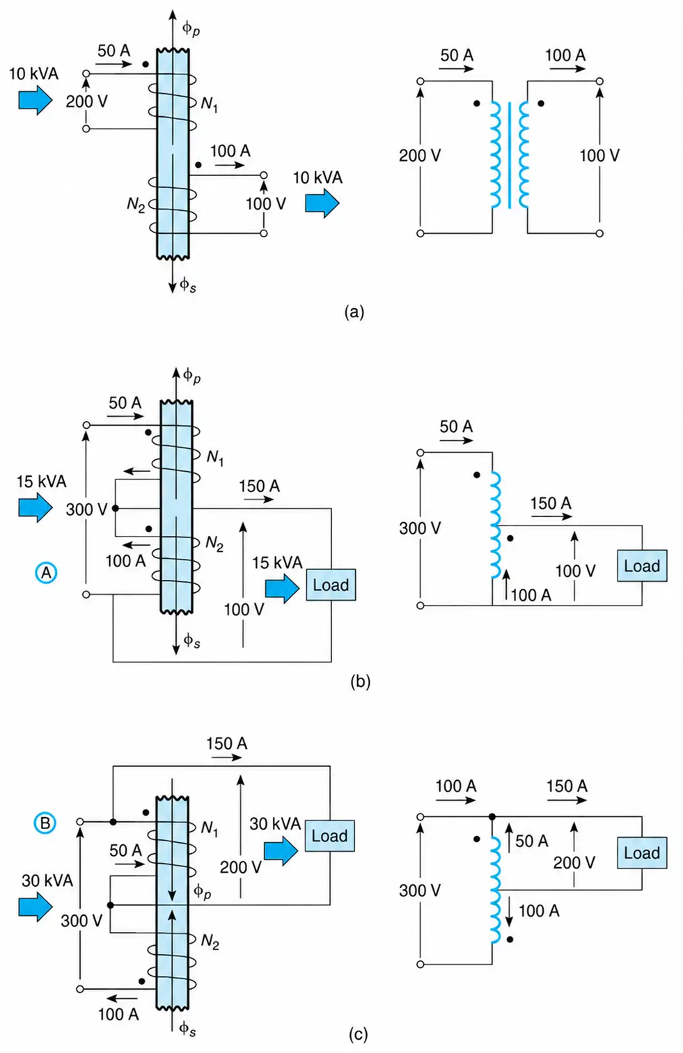
Figure 2-45 Transformer representations and their schematics. (a) A two-winding transformer. (b) Type A autotransformer connection. (c) Type B autotransformer connection.
In autotransformers, one single winding is used as the primary winding as well as secondary winding, as against two distinctly separate windings in a conventional power transformer. Autotransformers are smaller in size and more economical than two-winding transformers of the same rating. They are normally used for voltage-transformation ratios close to 1:1 and in Variacs, which provide a variable secondary voltage.
Understanding and analyzing autotransformers is simplified by noting the following:
1. The ampere-turns of each coil are the same whether the transformer is connected as an autotransformer or as a two-winding transformer. That is,
$$(NI)=\text{constant} \ \ \ \ \ (2.60)$$
In other words, the magnitude of the current through each coil remains the same, regardless of whether the transformer operates as an autotransformer or as a conventional two-winding transformer.
Referring to Figure. 2-45, the ampere-turns of each coil are the same in each of the three situations shown, but the complex power transferred from the supply to the load differs from one case to the next.
2. Since the current through each autotransformer winding is the same as in the conventional two-winding transformer, the winding loss remains the same. However, the efficiency of the autotransformer is increased if the output power is increased.
3. Neglecting losses, the complex power (kVA) at the input is equal to the complex power delivered to the output:
$$(\text{kVA})_{\text{input}}=(\text{kVA})_{\text{output}} \ \ \ \ \ (2.61)$$
The kVA transformation capability of the autotransformer is the same as that of the two-winding transformer. An autotransformer, however, delivers higher kVA than the conventional transformer because of the direct electrical connection between the primary and secondary windings. In other words, part of the output kVA is conducted from the primary to the secondary winding. The conducted kVA is referred to as untransformed kVA.
4. The two-winding conventional transformer has its primary and secondary circuits electrically isolated, while in the autotransformer electrical disturbances in the primary can be easily passed to the secondary through their direct electrical connection.
A two-winding transformer, as shown in Figure. 2-45, can be connected in two ways to supply a load as an autotransformer. The two different connections are identified as A and B. For reasons of comparison, the highlights of type A and B connections are summarized in Table 2-1. In both cases, the output voltage is smaller than the input voltage. However, when one of the voltage windings is reversed, the output voltage will be larger than the input voltage.
Table 2-1. Parameters of Two-Winding Transformers and Autotransformers
|
Parameter |
Conventional Two-Winding Transformer |
Autotransformer Connection Type A: Load across the Same Winding as in the Two-Winding Transformer |
Autotransformer Connection Type B: Load Connected across the Primary Winding of the Two-Winding Transformer |
|
Turns ratio |
$a = \frac{N_1}{N_2}$ |
a + 1 |
$\frac{a+1}{a}$ |
|
Winding voltage |
V |
V |
V |
|
Winding current |
I |
I |
I |
|
Efficiency |
High |
Higher |
Much higher |
|
Input short circuit current |
$\frac{1+a}{a}\, I_{sc}$ |
$a(a+1)\, I_{sc}$ |
|
|
kVA transformed |
S |
S |
S |
|
kVA untransformed (conducted) |
0 |
$\frac{S}{a}$ |
aS |
|
Total kVA Output |
S |
$S\left(\frac{a+1}{a}\right)$ |
$S(a+1)$ |
Example 2-8
A 480–120 V, 20 kVA, two-winding transformer with a leakage impedance of (0.02 + j0.05) per unit has an efficiency of 0.96 when it delivers rated current at 0.90 power factor lagging. This transformer is to be connected as an autotransformer to a 600 V source to supply a load at either 480 or 120 V. For each type of autotransformer connection determine:
a. The kVA rating of the autotransformer. What percent of this kVA passes through the autotransformer untransformed?
b. The efficiency at full-load and 0.90 power factor lagging.
c. The input current when the load is shorted. Compare the results with those of the two-winding operation.
Solution
This problem compares the essential parameters of a two-winding transformer with those of its autotransformer connections.
Type (A) Autotransformer Connection (Load across the 120 V Winding)
a. Referring to Figure. 2-46(b), the magnitude of the current through the input will be the current rating of the 480 V winding. That is,
$$I = \frac{20{,}000}{480} = 41.67\ \text{A}$$
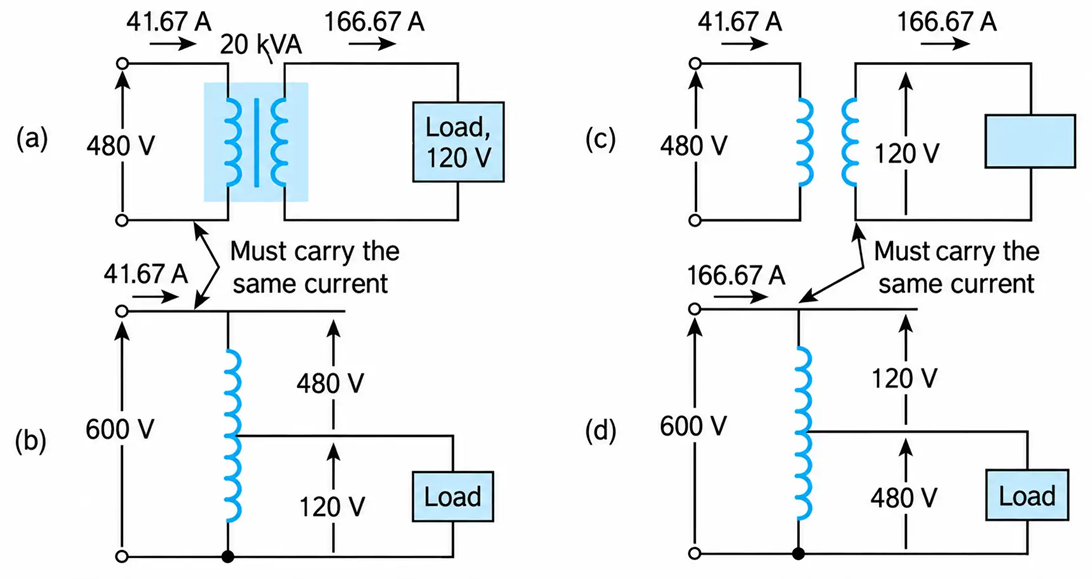
Figure 2-46 (a) and (b): Two-winding and autotransformer connection (type A). (c) and (d): Two-winding and autotransformer connection (type B).
Therefore, the input apparent power to the autotransformer is
$$S = 41.67(600)= 25\ \text{kVA}$$
Of these 25 kVA, 5 kVA pass unaltered, or untransformed, from input to output; the remaining 20 kVA are transformed, as in the case of the two-winding transformer connection. Thus,
$$\text{percentage of untransformed kVA} = \frac{5}{25}(100)= 20\%$$
b. The losses of the two-winding transformer are
$$\text{losses} = \text{power input} - \text{power output} = \frac{P_{\text{out}}}{\eta} - P_{\text{out}}$$
$$\text{losses} = 20{,}000(0.9)\left(\frac{1}{0.96} - 1\right) = 750\ \text{W}$$
For the autotransformer connection, the losses remain constant. Thus, the efficiency is
$$\eta = \frac{25(0.90)}{25(0.90) + 0.750} = 0.97$$
c. For the two-winding transformer, the magnitude of the short-circuit current is
$$I_{sc} = \left|\frac{1}{0.02 + j0.05}\right|= 18.57\ \text{pu}$$
For the HV winding, the current in amperes is
$$I_{sc} = 18.57(41.66)=773.73\ \text{A}$$
The leakage impedance, in ohms, is
HV side
$$Z_{bH} = \frac{(480)^2}{20{,}000} = 11.52\ \Omega$$
$$Z_H = (0.02 + j0.05)(11.52) = 0.62 \angle 68.2^\circ\ \Omega$$
LV side
$$Z_{bL} = \frac{(120)^2}{20{,}000} = 0.72\ \Omega$$
$$Z_L = (0.02 + j0.05)(0.72) = 0.04 \angle 68.2^\circ\ \Omega$$
In the case of the autotransformer, when the 120 V winding is shorted, the source of 600 V is applied across the 480 V winding. Thus, the magnitude of the short-circuit current is
$$I_{sc} = \frac{600}{0.62} = 967.16\ \text{A}$$
or, by using the appropriate relationship from Table 2-1.
$$I_{sc} = 773.73\left(\frac{1+a}{a}\right) = 773.73\left(\frac{5}{4}\right)= 967.16\ \text{A}$$
Type (B) Autotransformer Connection (Load across the 480 V Winding)
a. Referring to Figure. 2-46(d), the current through the 600 V source will be the rated current of the 120 V winding. That is,
$$I = \frac{20 \times 10^3}{120} = 166.67\ \text{A}$$
This current must pass through the input terminals. Therefore, the apparent input power for this type of autotransformer connection is
$$S = 166.67(600)= 100\ \text{kVA}$$
Of these 100 kVA, 80 kVA pass unaltered from the input to the output, while the remaining 20 kVA are transformed as in the case of the two-winding connection.
Expressing the untransformed kVA in percentage of the total output kVA, we have
$$(\text{kVA})_{\text{untr.}} = \frac{80}{100}(100) = 80\%$$
b. Since the losses are constant at 0.75 kW, the efficiency is
$$\eta = \frac{100(0.9)}{100(0.9) + 0.75}= 0.99$$
c. By shorting the load, the 600 V are applied across the 120 V winding. Thus, the magnitude of the short-circuit current is
$$I_{sc} = \frac{600}{0.04} = 15{,}474.6\ \text{A}$$
For comparison purposes, the results are summarized in Table 2-2. Check the results by using the applicable relationships given in Table 2-1.
Table 2-2. Summary of Results of Example 2-8
|
Autotransformer Connection |
|||
|
Parameter |
Two-Winding Transformer Connection |
Type A Load across 120 V |
Type B Load across 480 V |
|
Output kVA |
20 |
25 |
100 |
|
Efficiency |
0.96 |
0.97 |
0.99 |
|
Short-circuit current through the source in A |
773.7 |
967.16 |
15,474.6 |
Disadvantages of Autotransformers
The disadvantages of autotransformers are as follows:
- They are not economical for voltage rations larger than 2.
- They require primary protective devices of higher capacity.
- Because of the electrical conductivity of the primary and secondary windings, the lower voltage circuit is liable to be impressed upon by higher voltage. To avoid breakdown in the lower voltage circuit, it becomes necessary to design the low-voltage circuit to withstand higher voltage.
- The autotransformer has a common terminal between the primary and the secondary windings, and when the secondary is shorted, the voltage applied to the primary is much higher than its rated voltage. This results in higher short-circuit currents and thus requires more expensive protective devices.
- The connections on primary and secondary sides must necessarily be the same, except when using interconnected starring connections. This introduces complications due to changing primary and secondary phase angles, particularly in the case-by-case of the delta–delta connection.
- Because a common neutral in a star–star connected autotransformer, it is not possible to ground the neutral of one side only. Both of its sides must have its neutrals either grounded or isolated.
- It is more difficult to preserve the electromagnetic balance of the winding when voltage adjustment tappings are provided. It should be known that the provision of adjusting tapping on an autotransformer increases the frame size of the transformer considerably.
