VSC-HVDC Technology: Converter Operation, Configurations, Applications
Learn how VSC-HVDC systems operate, explore their key components and converter topologies, and understand why they are increasingly used in modern power transmission and offshore energy applications.
Recent developments of power electronic devices have led to the rise of self-commutated voltage source converters (VSC) in power system applications. This is mainly attributed to the development of the insulated gate bipolar transistor (IGBT), a device which combines the controllability of the MOSFET with the reliability and power rating of the BJT. Together with the increased computational power of digital signal processors (DSPs), it was possible to use this technology in power transmission. The first VSC-HVDC application was built at the end of the 1990s.
The full controllability and switching symmetry through both turn-on and turn-off operation allows the device to regulate power flow much more quickly than its predecessors. The utilization of solid-state devices virtually eradicates the risk of commutation failure. This technology also has the ability to absorb and generate both active and reactive power independently of one another. This eliminates the requirement for the expensive reactive power compensators used extensively within LCC-HVDC projects.
Further advantages are that there is no requirement for regulation of the short-circuit level as commutation can operate without an AC system voltage source. Also, the generation of harmonics is greatly reduced, minimizing the volume of filters required to absorb them.
An additional feature of the VSC is the capability to offer “blackstart” support. That is, restoring power without the aid of an external power source. This is advantageous in a wide area power outage as these power sources can be brought online first to begin the progressive resurrection of the network grid.
The VSC-HVDC transmission technique is experiencing great development. The first commercial voltage source converter (VSC)-HVDC was built 1997 on the island of Gotland. Since then, ratings and applications have progressed rapidly. The power and voltage for Gotland Light™ was 50 MW and ± 80 kV. Fifteen years later, power and voltage ratings have increased by a factor of 20 and 6 times, respectively—for example, the 2 × 1000 MW INELFE project between France and Spain (Figure 1) and the 500-kV Skagerrak 4 project between Norway and Denmark.
The first VSC-HVDC offshore converter station was installed in 2005 on the Troll A oil platform, while the first connection to an offshore wind farm was commissioned in 2010 with the Borwin system (Figure 2).
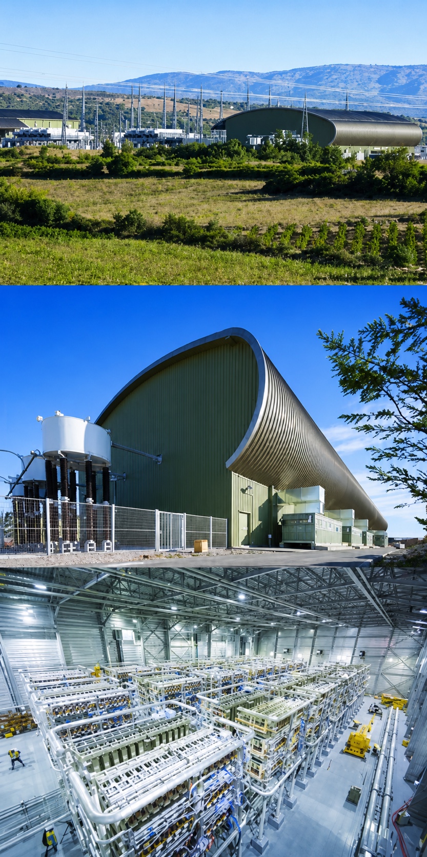
Figure 1 Converter station of the INELFE project.
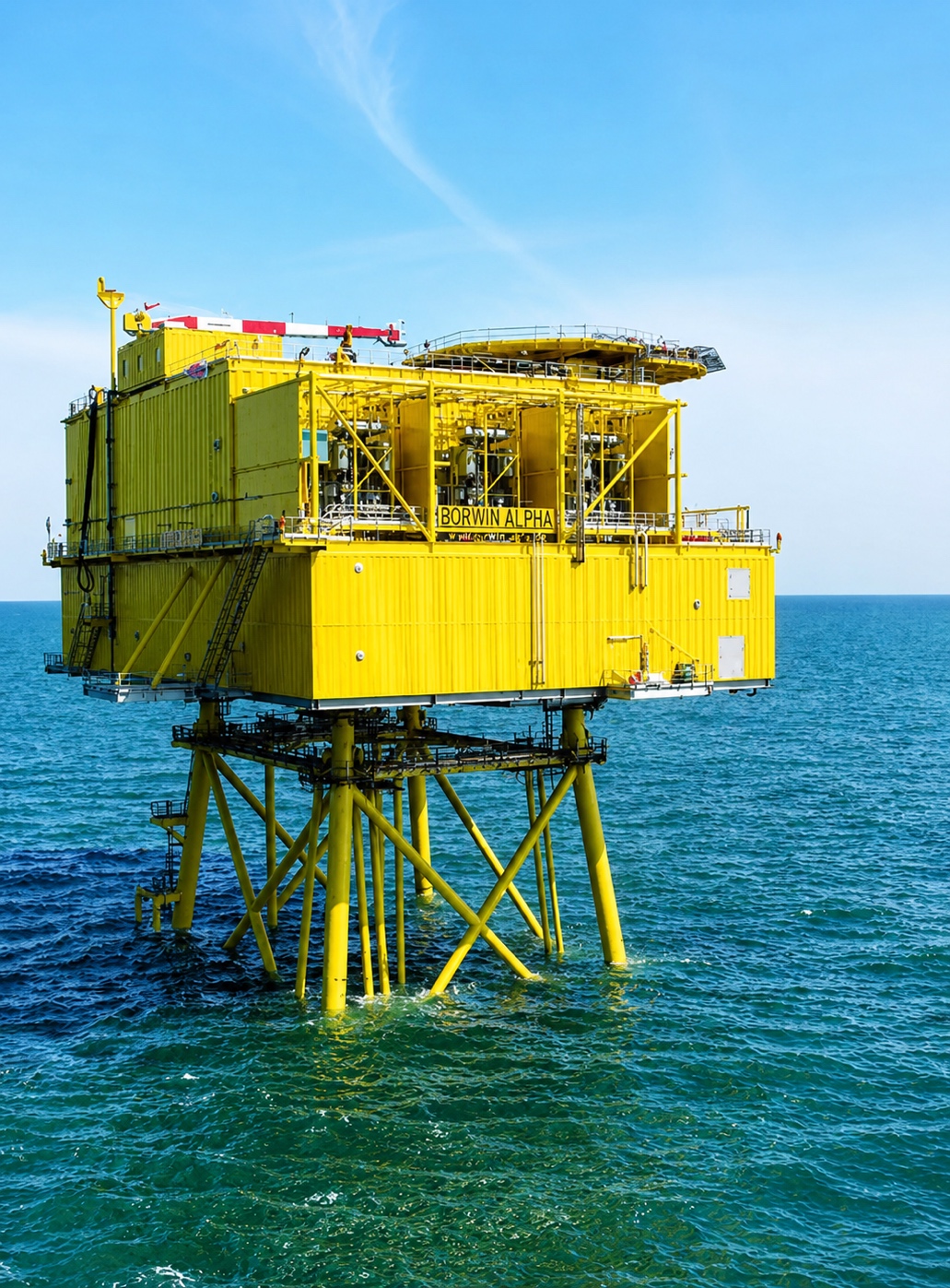
Figure 2 Borwin offshore VSC-HVDC converter station.
Although there is obvious potential for VSC-HVDC schemes to supersede the LCC-HVDC technology in certain instances, the foreseeable future of HVDC transmission will be a landscape whereby static power converters are chosen on a project by project basis depending on system requirements and control philosophy.
VSC-HVDC Converter Station Technology
A complete VSC-HVDC system consists of
- AC transformers, AC filters, phase reactors at the AC side and
- DC capacitors, DC cables, DC chopper, and DC switchgear at the DC side.
They are connected by the DC converter, which is built using power electronic switches. A typical topology of VSC-HVDC converter station is shown in Figure 3.
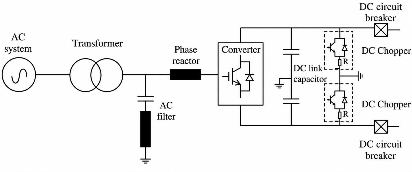
Figure 3 Main components of the VSC-HVDC system. The DC capacitors can be integrated in the converter itself, while the DC chopper and the DC circuit breaker are not standard components in a VSC-HVDC station.
Compared to the traditional LCC-HVDC system, the VSC-HVDC system is significantly smaller. This is due to the reactive power compensators and AC filters that are required in the LCC arrangement which are more voluminous compared to the VSC solution, resulting in a significantly smaller footprint.
Converter Configurations
Generally, three types of converter configurations have been mainly utilized for VSC-based HVDC systems:
- two-level converter,
- three-level neutral point clamped (NPC) converter, and
- modular multilevel converter.
Two-Level Converter with Pulse-Width Modulation (PWM)
The purpose of a power converter is to produce a sinusoidal AC voltage from a DC voltage which can be considered to be constant (inverter mode) and to reverse this process (rectifier mode). An effective technique to achieve the conversion can be the use of pulse-width modulation (PWM).
Switching devices at high frequency and averaging the output can build a near-sinusoidal wave at a specified frequency, which is achieved by modulating the width of the voltage pulse. If the input signal is a sinusoidal wave, this is called sinusoidal pulse-width modulation (SPWM). Figure 4 gives the waveforms of instantaneous output voltage and the fundamental output sinusoidal generated from a two-level converter using PWM. The output pulses have the same amplitude and different widths.
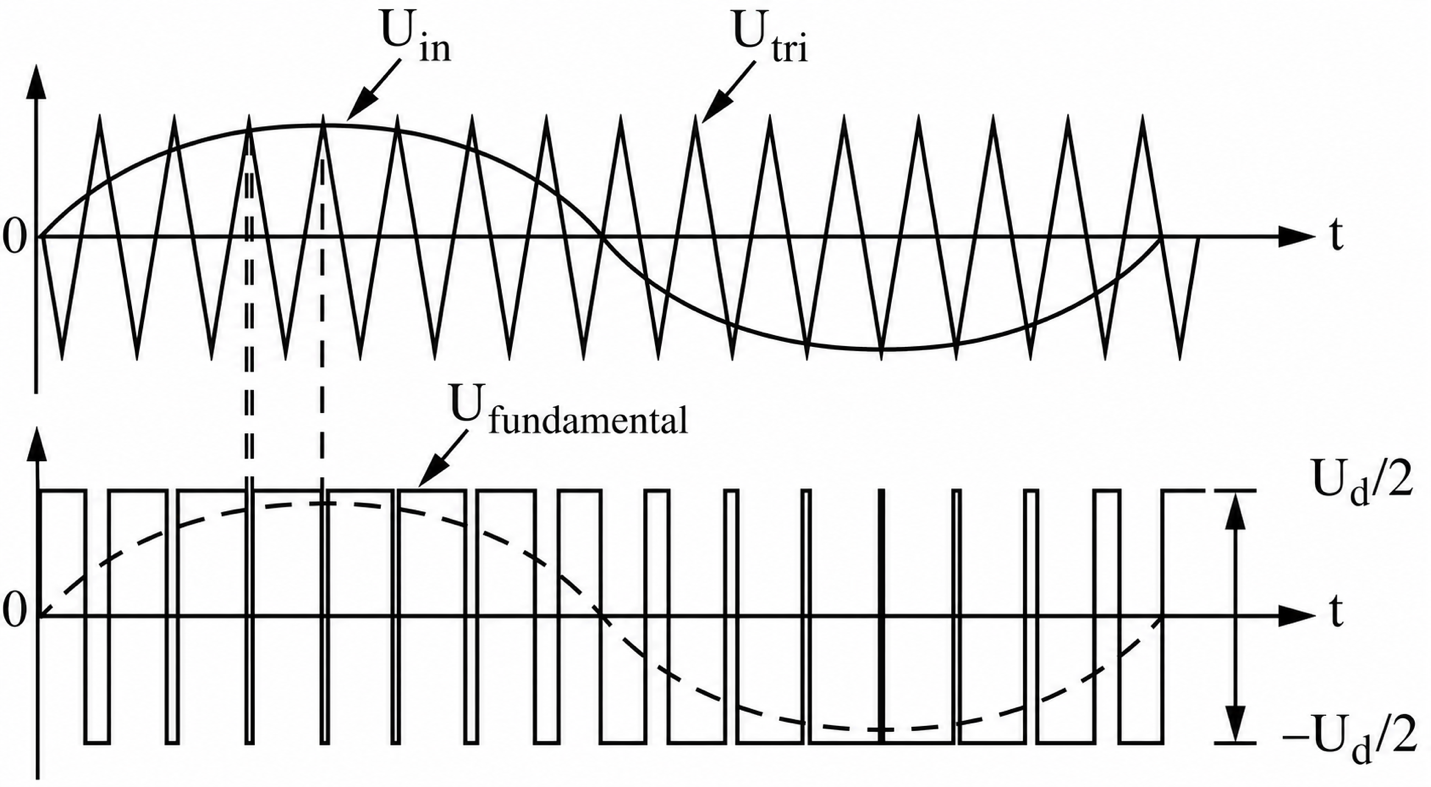
Figure 4 Typical waveforms of pulse-width modulation (PWM).
A key feature of PWM is that the triangle (carrier) signal frequency ftri must be higher than the frequency of the input signal fin. For a single-phase PWM the frequency modulation ratio mf is defined by
$$m_f=\frac{f_{\mathrm{tri}}}{f_{\mathrm{in}}}\ \ \ \ \ (1)$$
However, increasing the switching frequency will result in an increase of losses. A compromise for the switching frequency must be found to ensure that the PWM is efficient with reasonable low losses.
The amplitude of the sinusoidal signal is determined by a modulation ratio ma. which is expressed using the maximum amplitude of the input signal voltage Uin and the triangle (carrier) signal amplitude Utri:
$$m_a=\frac{U_{\mathrm{in}}}{U_{\mathrm{tri}}}\ \ \ \ \ (2)$$
The first VSC-HVDC-based technology, trademarked HVDC Light, was developed by ABB in 1997. A SPWM control philosophy is used to control the IGBT’s gate switching frequency producing a two-level AC waveform.
Switching frequencies between 1 and 2 kHz are used to balance the compromise of harmonics and switching losses. The switching instances can be varied in a style called optimum PWM. This method reduces the switching frequency as the current increases, which efficiently manages the switching losses across the converter valves while maintaining harmonic elimination.
In order to efficiently eliminate harmonics, switching frequencies are concentrated into a narrow band where small filters can be used. The Estlink between Estonia and Finland uses a two-level converter (with optimum PWM).
In two-level configurations, IGBTs are connected in series to increase the voltage level of the converter. As the instantaneous voltage over the individual components cannot exceed the component limits, these series-connected IGBTs need to switch at exactly the same moment, so that each individual IGBT carries the same voltage.
A high switching frequency can lead to high loss: For two-level PWM converters the losses can be up to 1.4% per converter, which is significantly higher than 0.8% of LCC HVDC technology.
Three-Level Neutral Point Clamped (NPC) Converter
PWM strategies used in a conventional inverter can be modified to use in multilevel converters. The switching frequency can be up to 2 kHz. This high frequency reduces the generated harmonics significantly, so that transformers with tertiary windings (such as with the 12-pulse configuration) are not needed. However, as each switching operation causes losses, the high switching frequency increases total power losses. Switching is the highest loss element in the converter station.
In order to lower the harmonic distortion of the output voltages, higher level converter bridges are used. A three-level neutral point clamped is used for the Murray Link (Australia). In Figure 5a a three-level VSC bridge is depicted, and a typical output voltage waveform of a three-level VSC can be seen in Figure 5b.
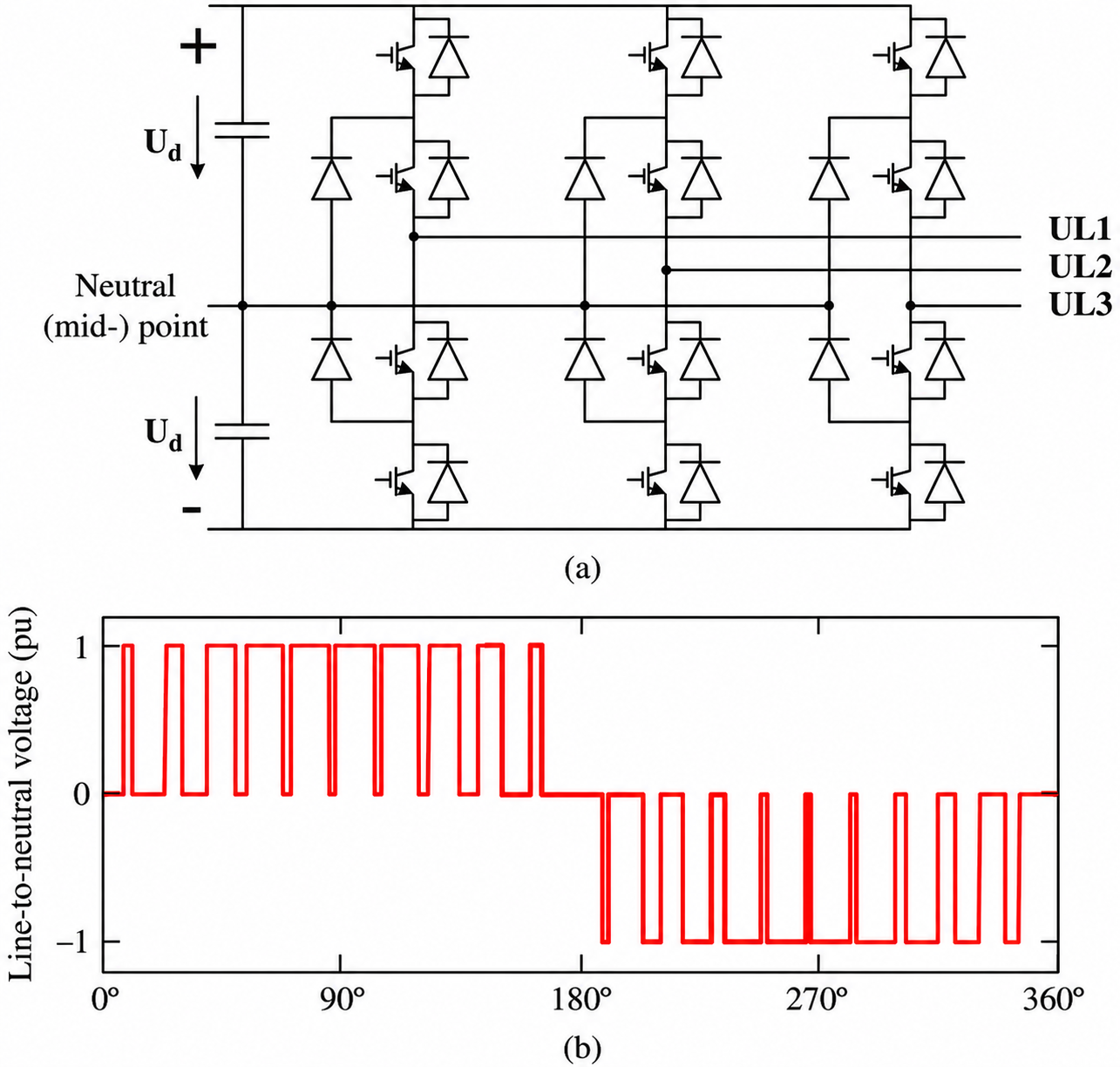
Figure 5 Three-level VSC-HVDC converter topology. (a) Scheme of a three-level three-phase VSC. (b) Voltage waveform of a three-level three-phase VSC with single phase output voltage (fswitch = 21 · fn).
Higher-level converter topologies (e.g., five-level, seven-level, etc.) are able to lower the harmonic distortion further and can lower the number of switching operations per switch. These higher-level converter topologies also promise lower switching losses. However, it becomes clear that the system complexity increases rapidly with the number of voltage levels. In practice, only two-and three-level converters are currently in use. When higher-level topologies are desired, the current industry practice is to resort to multilevel converters that stack different modules.
Modular Multilevel Converters
A PWM scheme utilizing a two-voltage-level arrangement can suffer from high power losses. Modular multilevel converters (MMCs) are used in VSC HVDC to reduce losses by stepping through voltage levels to build output waveform. The MMC concept was proposed in Germany by Marquardt and was firstly implemented by Siemens in the Trans Bay Cable project in the United States. The converters can be based on two different cell principles:
- half-bridge
- full-bridge
The VSC-HVDC power converters from Siemens, Alstom grid, and ABB [4th generation: cascaded two-level (CTL)] are based on this technology.
Half-Bridge Configuration
A multilevel converter which utilizes half-bridge modules in series is shown in Figure 6. There is a separate small capacitor of each module. Each bridge is supplied by a separate DC source.
Left diagram shows 2 IGBT's connected with a capacitor. Right diagram shows cascaded configuration of 2 loads and SM sub(1) to SM sub(n).
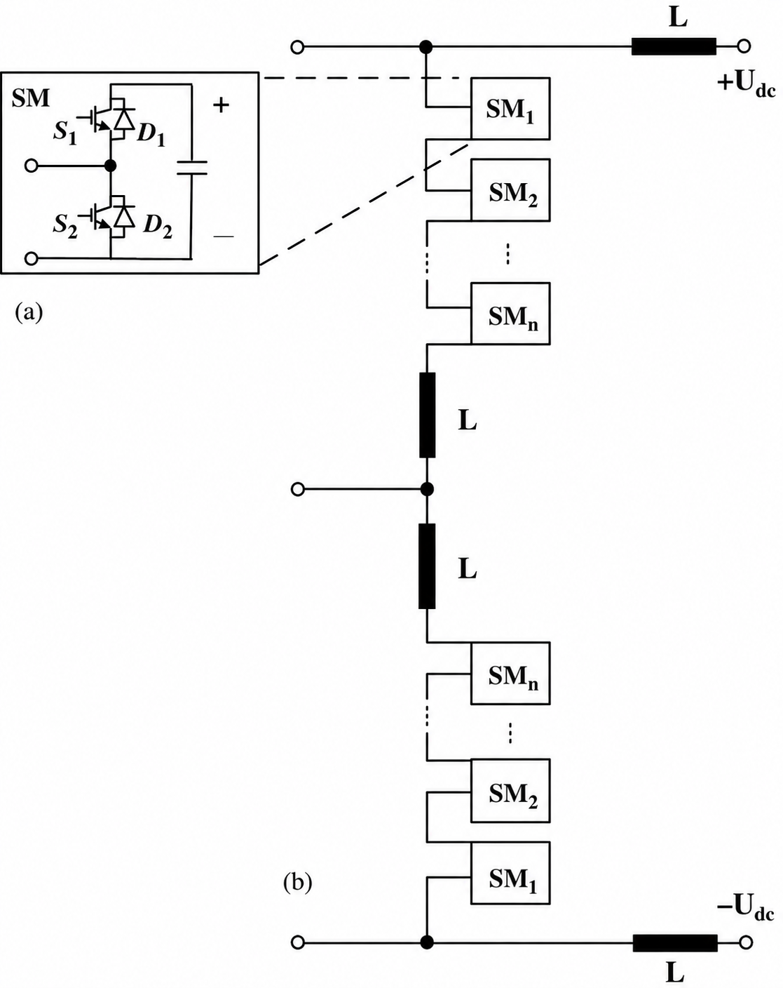
Figure 6 Schematic of a half-bridge module and a cascaded configuration.
The positive voltage of each module is achieved by turning on the upswitch—for example, S1 in Figure 6a, while a “zero” voltage can be achieved by turning on the low-switch, S2 in Figure 6a. The half-bridge module cannot generate a negative voltage. The converter output voltage can be increased by many modules connected in series.
By switching each module on/off once every period of the sinusoidal signal at given instances, many small voltage steps are formed, which then build the stepwise AC waveform, as shown in Figure 7.
Waveforms show a combination of sine wave with staircase structure at the top and bottom part represents corresponding rectangular waves obtained from 11-level cascade converter with 5 separate DC sources.
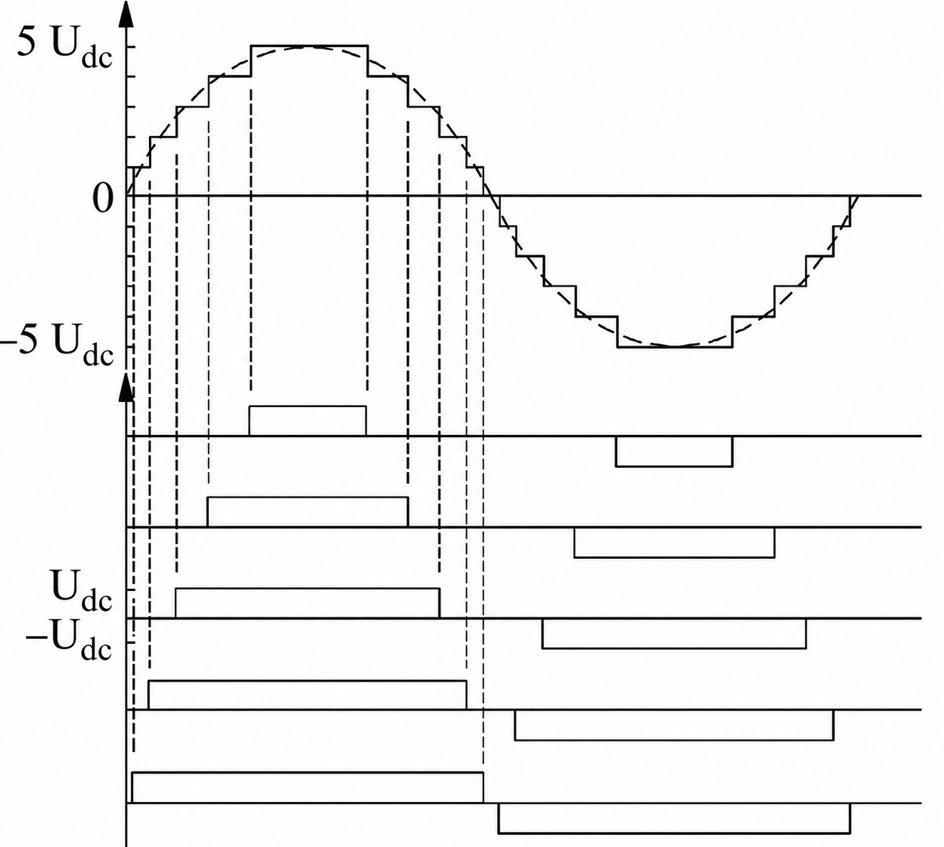
Figure 7 Output waveform generated from an 11-level cascade converter with five separate DC sources.
In comparison of conventional two-level converter technologies, this multi-modular configuration shows many advantages including low switching losses and low level of HF noise because of low switching frequency. The modular nature of the converter allows easy manufacture and maintenance; however, the quantity of the separate DC sources required can be problematic.
This approach of using modules maximizes the output voltage of the converter because many modules can be used in series; however, there are some limitations due to the conductor rating and speed of the logic hardware. A methodology to control each individual submodule is needed to calculate the required converter leg voltages, choose which submodules to switch, allow the control of active and reactive power, and balance the submodules’ voltage. The Trans Bay Cable connection, which was commissioned in 2010, utilizes this technology.
Full-Bridge Configuration
The module in a multilevel converter can also be achieved by employing full bridge (also called H-bridge) modules in series as shown in Figure 8. The positive and negative voltage levels are achieved by charging the mid-capacitor in either direction—for example, by turning on S1/S4 or S2/S3 in Figure 8a—while a “zero” voltage can be achieved by bypassing the capacitor altogether—for example, by turning on S1/S3 or S2/S4 in Figure 8a. The modular nature of the converter allows easy manufacture and maintenance; however, the quantity of the separate DC sources required can be problematic as well, which is the same with the cascaded half-bridge configuration.
Left diagram shows 4 IGBT's connected with a capacitor. Right diagram shows cascaded configuration of 2 loads and SM sub(1) to SM sub(n).
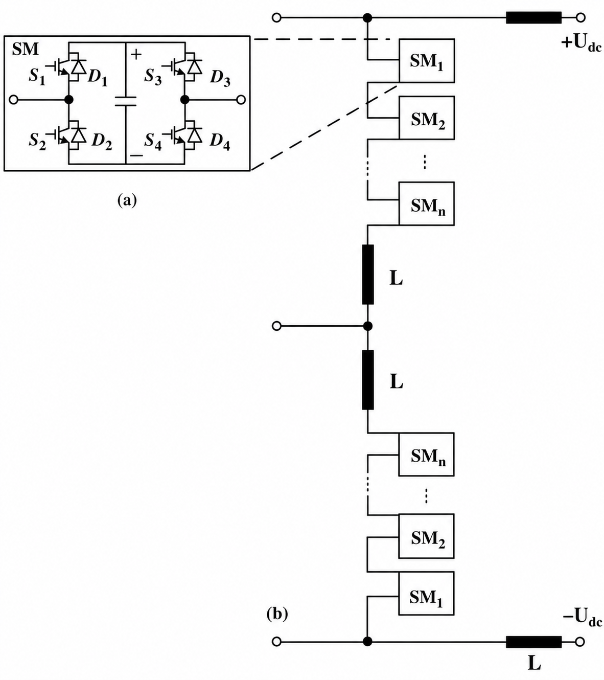
Figure 8 Schematic of full or H-bridge module and a cascaded configuration.
By switching each module on/off at given instances, many small voltage steps are formed, which then build stepwise AC waveforms by the addition of small voltage steps generated by different full-bridge. Increasing the number of modules will lead to a larger number of smaller steps and closer synthesis of the desired sinusoidal wave.
Alternate-Arm Converter (AAC)
Alstom Grid has developed an alternative concept called Alternate-Arm Converter (AAC) (commercial name: HVDC MaxSine™). Other objectives of the AAC are to push further the characteristics of the traditional VSC by cutting the number of H-bridge cells, reducing overall losses, and gaining the ability to control DC fault current.
As illustrated in Figure 9, each phase of the converter consists of two arms, each with a stack of full-bridge cells, a director switch, and a small arm inductor.
- The stack of cells is responsible for the multi-step voltage generation, as in a multi-level converter. Since full-bridge cells are used, the voltage produced by the stack can be either positive or negative; thus, the converter is able to push its AC voltage higher than the DC terminal voltage if required.
- The director switch is composed of IGBTs connected in series in order to withstand the maximum voltage which could be applied across the director switch when it is in the open state. The main role of this director switch is to determine which arm is used to conduct the AC current.
The key feature of this topology is to use essentially one arm per half-cycle to produce the AC voltage. By using the upper arm to construct the positive half-cycle of the AC sine wave and the lower arm for the negative part, the maximum voltage that each stack of cells has to produce is equal to half of the DC bus voltage, which is approximately half the rating of the arm of the MMC. The aim of the AAC is to reduce the number of cells, hence the volume and losses of the converter station.
Diagram shows alternate arm converter which includes stack of cells SM sub(1) to SM sub(n), director switch and arm inductor connected to loads and capacitors.
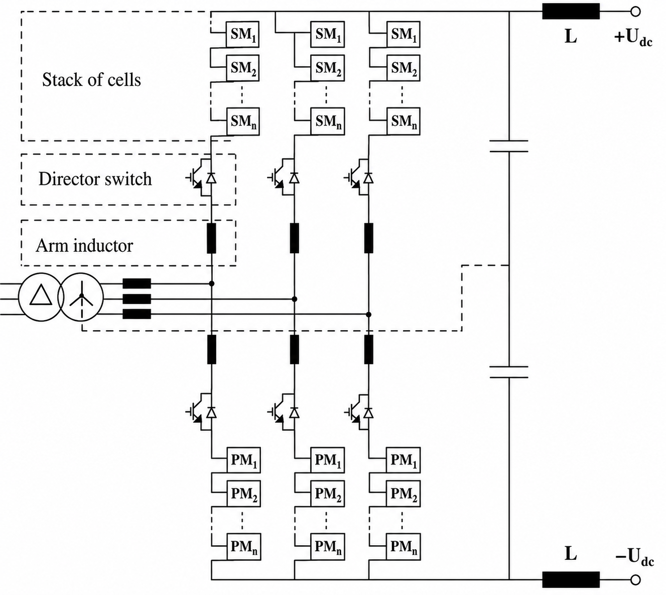
Figure 9 Schematic of the alternate arm converter.
Furthermore, the converter is still very responsive in case of a fault. Half-bridge cells are normally used in preference to full-bridge cells in order to reduce the number of devices in conduction at any time and, therefore, reduce the conduction power loss. Even if this choice is justified by the large cost associated with the power losses, it also means that the converter is vulnerable to a dc-side fault in a similar way to a two-level converter whereas an H-bridge version would not be.
The inability of half-bridge cells to produce a negative voltage results in the conduction of the antiparallel diodes connected to the IGBTs, thus creating an uncontrollable current path in case of a collapse of the DC bus voltage. DC circuit breakers for high-power applications are still under development. Therefore, H-bridge MMC or AAC will be options for future MTDC grid.
Comparison
A summary of comparison between VSC HVDC based on two-level converters and multilevel converters is given in Table 1. In general, multilevel converters have the disadvantage of involving a larger footprint than their two-level counterparts while maintaining an advantage in minimizing stresses. The commissioning projects using multilevel topologies in the coming years is a testament of the success of the technology’s approach.
Table 1 Comparison of VSC-HVDC Topologies
|
Two-Level Converter |
Multilevel Converter |
|
Series-connected IGBTs and PWM |
Multi-modular in cascaded connection |
|
Conceptually simple circuit |
Easily scalable |
|
Requires PWM |
More complex controls |
|
High switching losses |
Low switching losses |
|
Harmonic problems from PWM |
Virtually no harmonics |
VSC-HVDC Practical Applications
VSC-HVDC schemes are commonly referred to with their brand names: HVDC Light (ABB), HVDC Plus (Siemens), or HVDC MaxSine (Alstom Grid).
The first VSC HVDC installation started operation in 1997 and has a rating of 50 MW, with a ± 80 kV DC voltage, and was a prototype. Currently, there are over 10 active installations worldwide with different technologies (Table 2). The table shows the evolution in converter technology used in a selection of commercial projects: from two-level and three-level NPC towards multilevel converters.
Table 2 The Evolution of VSC-HVDC Technology
|
Project |
Year |
Converter Type |
Power Rating (MW) |
Converter Losses (%) |
DC Voltage (kV) |
Supplier |
|
Gotland |
1997 |
Two-Level |
50 |
3 |
±80 |
ABB |
|
Eagle Pass |
2000 |
Three-Level Diode NPC |
36 |
2.2 |
±15.9 |
ABB |
|
Estlink |
2006 |
Two-Level with PWM |
350 |
1.4 |
±150 |
ABB |
|
Trans Bay Cable |
2010 |
MMC |
400 |
1 |
±200 |
Siemens |
|
Nanao 3-terminal DC grid |
2013 |
MMC |
200/100/50 |
— |
±160 |
Multiple |
|
SW Link |
2014IP |
MMC |
2×720 |
— |
±300 |
Alstom Grid |
|
Dolwin2 |
2015IP |
MMC |
900 |
— |
±320 |
ABB |
Key Takeaways
VSC-HVDC technology has expanded the capabilities of high-voltage direct current transmission by providing independent active and reactive power control, reduced harmonic distortion, and improved operation in weak grids. Advances in IGBT devices and modular multilevel converters have enabled compact, efficient, and highly flexible HVDC links for applications ranging from interconnections to offshore wind integration. As renewable energy deployment increases and power systems become more interconnected, VSC-HVDC systems are expected to play an increasingly important role in improving grid stability, reliability, and long-distance power transfer. Their versatility and scalability make them one of the key enabling technologies for future low-carbon electricity networks.