Electric Motor Control
Circuit Layout, Connections, and Symbols
-
Question 1
Identify the following symbols.
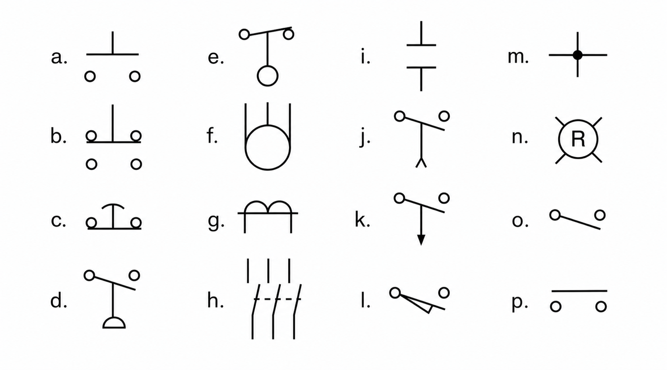 Reveal answer
a. Normally open, momentary contact push button
b. Double-acting, momentary contact push button
c. Mushroom head, normally closed, momentary contact push button
d. Normally open pressure switch
e. Normally closed float switch
f. Three-phase squirrel cage motor
g. Current transformer
h. Three-phase disconnect switch
i. Normally open contact
j. Normally open, on-delay timer contact
k. Normally open, off-delay timer contact
l. Normally open limit switch
m. Node point showing connected conductors
n. Red pilot light
o. Normally open switch (single-pole single-throw switch)
p. Double-break switch
-
Question 2
Electrical symbols usually conform to which standard?
Reveal answerIn North America, electrical symbols commonly follow the IEEE 315 / ANSI Y32.2 standard for electrical and electronic diagrams. For industrial control diagrams specifically, a commonly referenced NEMA standard is:
NEMA ICS 19 — Diagrams, Device Designations, and Symbols for Industrial Control and Systems
-
Question 3
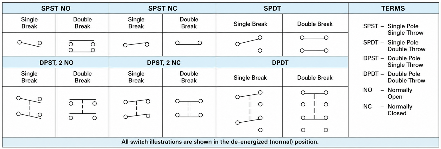
What do the following abbreviations stand for?
a. SPST
b. SPDT
c. DPST
d. DPDT
e. NO
f. NC
Reveal answera. single-pole single-throw
b. single-pole double-throw
c. double-pole single-throw
d. double-pole double-throw
e. normally open
f. normally closed
-
Question 4
Why is a circle most often used to represent a coil in a motor control schematic?
Reveal answerA circle is most often used to represent a coil in a motor control schematic because it provides space for letters and/or numbers to be written inside the symbol to identify the coil. These markings help distinguish different relays, contactors, timers, and other control devices within the circuit.
-
Question 5
When reading a schematic diagram, are the control components shown as they should be when the machine is turned off or de-energized, or are they shown as they should be when the machine is in operation?
Reveal answerControl symbols in a schematic diagram are shown as they would appear when the circuit is de-energized or turned off. This standard method makes it easier to understand the normal condition of switches, contacts, relays, and other control components before power is applied.
-
Question 6
In which diagram do the physical locations of the wiring and the devices match the drawing?
Reveal answerA wiring diagram matches the physical locations of the wiring and devices as they are actually installed. It shows how components are physically connected, making it useful for equipment installation, troubleshooting, and field wiring.
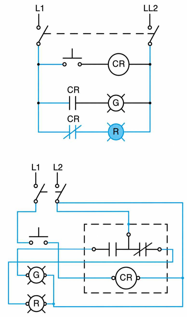
A single-pole, double-throw (SPDT) control relay schematic wiring diagrams.
-
Question 7
Which diagram conveys as much information as possible with the least amount of confusion?
Reveal answerThe line diagram, also called the elementary or schematic diagram, conveys the greatest amount of information with the least amount of confusion. It shows the electrical operation of the circuit in a simple, organized form, making it easier to understand how the control system functions.
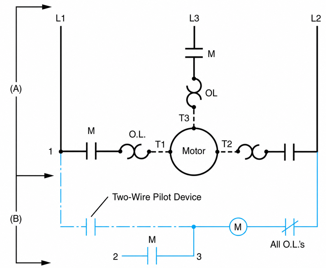
Line diagram of starter. (A) Line diagram showing the simplicity of the power circuit for the line voltage starter; (B) completed control wiring elementary style. Broken lines and motor are external field wiring that completes the circuit.
-
Question 8
A motor nameplate reads 230/460 volts, 30-15 amperes. When connected to a 460-volt supply, how much current will the motor draw fully loaded?
Reveal answerA dual-voltage motor nameplate reading: $230/460 V, 30/15 A$
means:
- At 230 V, the motor draws 30 A
- At 460 V, the motor draws 15 A
Therefore, when connected to a 460-volt supply, the motor will draw: $15\ \text{A}$
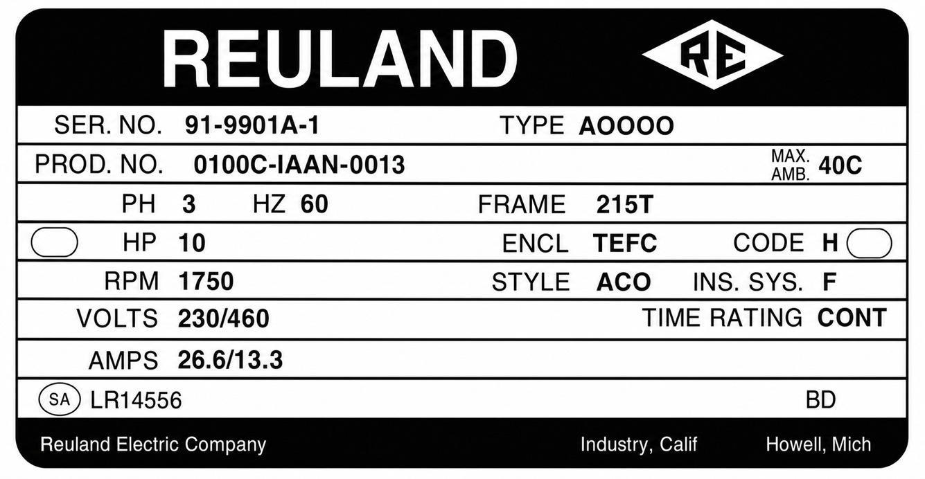
Standard three-phase motor nameplate.
-
Question 9
To what does the code letter on a motor nameplate refer?
Reveal answerThe code letter on a motor nameplate refers to the motor’s locked-rotor kVA per horsepower. It indicates the amount of inrush current the motor draws when starting with the rotor stationary.
