Electronic Variable Speed Drives
VFD Installation
-
Question 1
When mounting a VFD to a vertical surface, should the VFD be mounted vertically or horizontally, or does it matter? Why?
Reveal answerThe VFD should be mounted vertically to ensure proper air flow. Also, the surrounding space should be kept free of any obstructions or blockages to the flow of air around the drive. This is also important if two or more drives are to be mounted in close proximity to one another, such as side by side, or above and below.
-
Question 2
What three things are accomplished by grounding a VFD?
Reveal answerThe purpose of grounding a VFD is to accomplish three things: (1) should an electrical fault occur, exposed parts may become energized with dangerous voltage levels. Grounding these parts will limit the voltage to ground potential; (2) should a ground fault condition occur, proper grounding will promote proper overcurrent device operation; and (3) grounding will aid in the suppression of electrical interference.
-
Question 3
Explain the difference between a safety-ground PE and a shield ground.
Reveal answerThe safety-ground PE is the electrical connection that bonds the metal chassis of the VFD to Protective earth. The shield ground is the termination point of the shield wires from shielded cables.
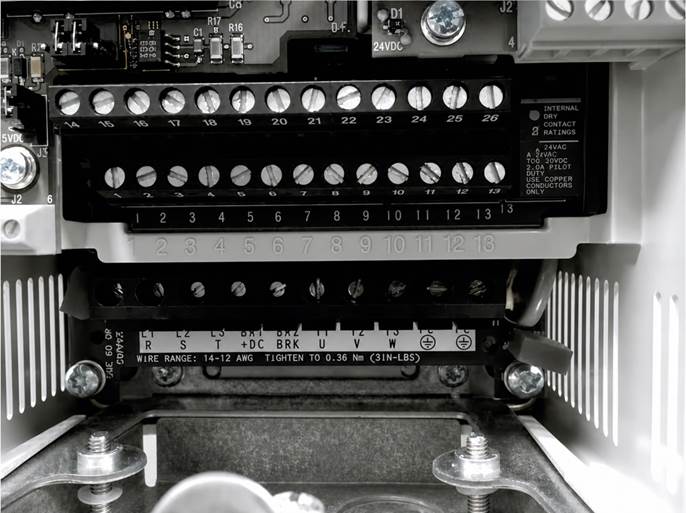
Safety ground connection on an Allen-Bradley Power Flex® 70 VFD.
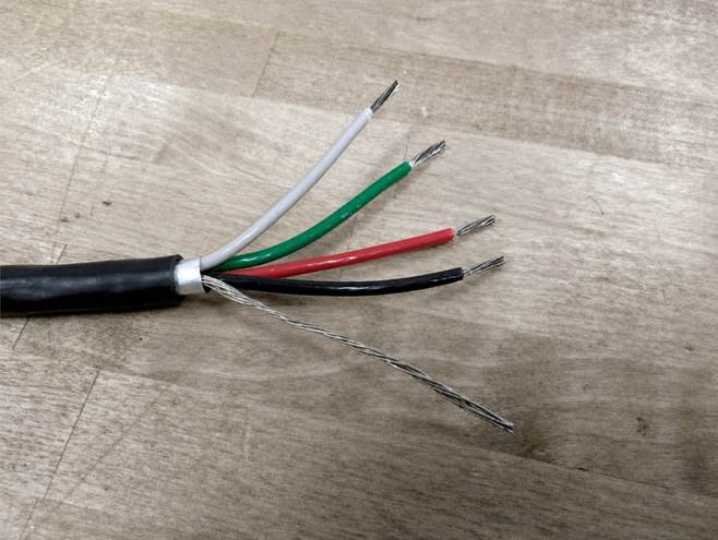
Shielded power cable.
-
Question 4
What is the effect of operating a three-phase VFD from single-phase power?
Reveal answerMost VFDs require three-phase power to operate within specifications. Some VFDs are also approved to operate from single-phase power. When operating from single-phase power, the output power of the drive must be derated. Typically, a VFD is derated by 50 percent when operated from a single-phase power source. This means that a VFD operating from three-phase power and rated at 10 HP will need to be derated to 5 HP when operated from a single-phase power source.
-
Question 5
What is the maximum amount that the source voltage can exceed the voltage rating of the VFD?
Reveal answerQuite often VFDs are connected to an inappropriate supply voltage. For example, it is not unusual for a VFD rated 208 V to be connected to a 240 V supply. Likewise, a 440 V rated VFD may be connected to a 460 V or even a 480 V source.
Usually, the source voltage should not exceed the voltage rating of the VFD by more than 10 percent. For a VFD rated at 208 V, the maxi-mum supply voltage is 229 V (208 3 10% = 20.8 + 208 = 229). Obviously, the 208 V VFD, when connected to the 240 V supply, is receiving excess voltage and should not be used. For a 440 V VFD, the maximum supply voltage is 484 V (440 3 10% + 440 = 484)
-
Question 6
What precaution should you take when routing the power cable from the source to the VFD?
Reveal answerThe cable that is used to supply power to the VFD is typically a three-conductor with ground cable. A main concern involves the routing of this cable. Care should be taken to avoid long, parallel runs with sensitive circuits. Generally maintaining a separation of 0.3 meters for every 10 meters of length provides sufficient separation to prevent coupling between circuits.
-
Question 7
What precaution should you take when routing the power cable from the VFD to the motor?
Reveal answerThe shield (drain) wire should be connected to the motor frame at the motor end of the cable and at the Shield terminal at the VFD end of the cable. It is also good practice to limit the length of the motor cable to no more than 30 meters between the VFD and the motor.
-
Question 8
What precaution should you take when routing I/O cable between the device and the VFD?
Reveal answerThe cable used to connect input and output (I/O) devices to the VFD can vary between a two-conductor shielded cable and multiconductor shielded cable. Cable with multiple individual shielded pairs may also be used.
Shielding is absolutely necessary to prevent electrical interference from entering the I/O cable and causing unexpected results. The shield (drain) wire in the I/O cable should be grounded at the device end only. Do not ground the cable at the VFD. Do not ground the cable at both ends. Only ground the cable at the device end of the cable.
Also, the routing of this cable is very important. Care should be taken to avoid long, parallel runs with power circuits. Generally maintaining a separation of 0.3 meters for every 10 meters of length provides sufficient separation to prevent coupling between circuits.
-
Question 9
What is the maximum allowable percent imbalance between phases that is allowed?
Reveal answerThe maximum allowable percent imbalance between phases is 2%. To determine if an imbalanced phase condition exists, you will need to do the following:
1. Measure and record the phase voltages (L1 to L2, L2 to L3, and L1 to L3).
2. Add the three voltage measurements from step 1 and record the sum of all phase voltages.
3. Divide the sum from step 2 by 3 and record the average phase voltage.
4. Now, subtract the average phase voltage obtained in step 3 from each phase voltage measurement in step 1 and record the results. (Treat any negative answers as positive answers.) These values are the individual phase imbalances.
5. Add the individual phase imbalances from step 4 and record the total phase imbalance.
6. Divide the total phase imbalance from step 5 by 2 and record the adjusted total phase imbalance.
7. Now, divide the adjusted total phase imbalance from step 6 by the average phase voltage from step 3 and record the calculated phase imbalance.
8. Finally, multiply the calculated phase imbalance from step 7 by 100 and record the percentage of total phase imbalance.
Consider an example involving a 440 V, three-phase supply to a VFD to see how this process works:
1. L1 to L2 = 432 V; L2 to L3 = 435 V; and L1 to L3 = 440 V.
2. The sum of all phase voltages equals 432 V + 435 V + 440 V, or 1,307 V.
3. The average phase voltage is equal to 1,307 V 4 3, or 435.7 V.
4. To find the individual phase imbalances, we subtract the average phase voltage from the individual phase voltages and treat any negative values as positive. So L1 to L2 = 432 V–435.7 V, or 3.7 V, L2 to L3 = 435 V–435.7 V, or 0.7 V; and L1 to L3 = 440 V–435.7 V, or 4.3 V.
5. Now, we find the total phase imbalances by adding the individual phase imbalances: 3.7 V + 0.7 V + 4.3 V = 8.7 V.
6. To find the adjusted total phase imbalance, we divide the total phase imbalance by 2: 8.7 V 4 2 = 4.35 V.
7. Next, we find the calculated phase imbalance by dividing the adjusted total phase imbalance by the average phase voltage: 4.35 V 4 435.7 V = 0.00998.
8. Finally, we multiply the calculated phase imbalance by 100 to find the per-cent total phase imbalance: 0.00998 3 100 = 0.998%.
In this example, we are within tolerances, and the differences in the phase voltages should not cause any problems. In fact, as long as the percent total phase imbalance does not exceed 2 percent, we should not experience any difficulties as a result of the differences in phase voltages.
