How to Read a Transformer Nameplate
A transformer’s nameplate provides the electrical, thermal, and construction information needed for its installation, operation, and maintenance. It identifies the manufacturer’s assigned ratings and operating limitations. These ratings must be interpreted together: loading capability depends not only on kVA, but also on cooling, ambient temperature, altitude, and operating conditions.
Although nameplate requirements vary with transformer type and applicable standards, the following details are particularly important.
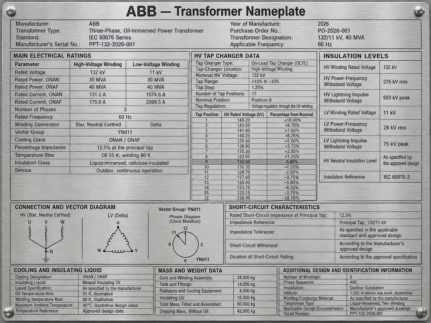
Figure 2-60 Transformer Nameplate Details
Apparent Power Rating in kVA
The apparent power rating indicates the transformer’s designed load-carrying capability. Transformers are rated in kilovolt-amperes (kVA) or megavolt-amperes (MVA), rather than kilowatts, because their thermal limitations primarily depend on voltage and current, not the load’s power factor.
For a single-phase transformer:
$$S=\frac{VI}{1000}\quad\text{kVA}$$
For a balanced three-phase transformer:
$$S=\frac{\sqrt{3}V_{LL}I_L}{1000}\quad\text{kVA}$$
Here, $V_{LL}$ is the line-to-line voltage and $I_L$ is the line current.
Operation within the marked kVA rating generally avoids excessive temperature rise provided the specified service conditions are satisfied. High ambient temperature, restricted ventilation, harmonic currents, or failed cooling equipment can cause overheating even below rated kVA.
A transformer designated:
$$1500/2000\ \text{kVA}$$
may have a natural-cooling rating of 1500 kVA and a forced-air rating of 2000 kVA. The higher rating is available only when the designated cooling equipment operates correctly.
Similarly, ratings of:
$$12/16/20/22.4\ \text{MVA}$$
must be read alongside their associated cooling and temperature-rise designations. The first three values might represent natural cooling and successive forced-cooling stages. However, these increases are manufacturer-assigned ratings, not universal allowances for adding fans.
The 22.4 MVA rating might correspond to an additional permitted temperature-rise condition. Upgraded insulation alone does not automatically authorize a 12% increase: bushings, leads, tap changers, cooling equipment, and other components must also support that rating.
Impedance in Percent
The percentage impedance represents the magnitude of the transformer’s equivalent series impedance, consisting of winding resistance and leakage reactance. It excludes the magnetizing branch.
It also indicates the percentage of rated voltage required to circulate rated current when the opposite winding is short-circuited under specified test conditions.
For example, a transformer with 6% impedance requires approximately 6% of rated voltage to produce rated current during its short-circuit test.
The corresponding impedance in ohms, referred to a selected winding, is:
$$Z=\frac{Z\%}{100}\frac{V_{LL}^{2}}{S}$$
For a three-phase transformer, (S) is the total three-phase rating in VA and $V_{LL}$ is that winding’s rated line-to-line voltage.
Percentage impedance is important for voltage regulation, fault-current calculations, protection coordination, and parallel operation. Neglecting upstream impedance, a 6% impedance gives an approximate terminal short-circuit current of:
$$I_{SC}\approx\frac{100}{6}I_{\text{rated}} =16.7I_{\text{rated}}$$
The physical impedance does not change simply because a different cooling rating is used. However, winding resistance changes with temperature, and percentage impedance changes when expressed on a different power base. Always check the nameplate’s stated reference rating, tap position, and temperature.
Efficiency in Percent
Transformer efficiency is the ratio of real output power to real input power:
$$\eta=\frac{P_{\text{out}}}{P_{\text{in}}}\times100%$$
The principal losses are no-load losses, mainly associated with the core, and load losses, including winding resistance and stray losses. No-load losses remain approximately constant at fixed voltage and frequency, while load losses increase approximately with current squared.
Efficiency depends on loading, power factor, temperature, and transformer design. Consequently, an efficiency figure is meaningful only when its test conditions are stated; it should not automatically be interpreted as full-load efficiency at unity power factor.
Efficiency may appear in technical documentation rather than on the nameplate itself. Many modern power and distribution transformers exceed 98% efficiency at specified operating points.
“Off-Load” Tap Changers
Tap changers alter the effective number of winding turns and therefore the transformation ratio. A common arrangement provides five positions:
- Nominal
- ±2.5%
- ±5%
An off-load tap changer is more precisely described as a de-energized tap changer. It must not be operated while the transformer is energized, even if it supplies no load. Isolation and the manufacturer’s safety procedures are essential.
Tap selection requires careful interpretation. On a typical high-voltage winding, selecting a higher-voltage tap increases the effective primary turns and reduces secondary voltage for a fixed supply voltage. A lower-voltage tap generally raises secondary voltage. Therefore, positive and negative labels should not be interpreted without consulting the connection diagram.
On-load tap changers, by contrast, are specifically designed to change taps while energized and carrying load.
Winding Connection—Rated Voltages
Three-phase transformer nameplates identify the winding connections, commonly delta $(\Delta)$ or star $(Y)$, and their rated voltages. Three-phase voltage ratings are normally line-to-line values unless otherwise specified.
For a star-connected winding:
$$V_{\text{phase}}=\frac{V_{LL}}{\sqrt{3}}$$
For a delta-connected winding, phase voltage equals line-to-line voltage. Consequently, the winding turns ratio is not always identical to the ratio of nameplate line voltages, particularly for delta–star transformers.
The vector group provides additional information about winding connections, neutral availability, and phase displacement. For example, Dyn11 identifies a delta high-voltage winding, a star low-voltage winding with an accessible neutral, and a clock-11 phase displacement.
These details are essential when connecting transformers in parallel. An accessible neutral does not itself specify the grounding method; grounding must follow the system design and applicable requirements.
Cooling Class and Temperature Rise
Cooling designations identify how heat is transferred from the windings to the surrounding environment. Common liquid-immersed transformer designations include:
- ONAN: Oil Natural Air Natural.
- ONAF: Oil Natural Air Forced.
- OFAF: Oil Forced Air Forced.
- ODAF: Oil Directed Air Forced.
Dry-type transformers commonly use AN for natural-air cooling and AF for forced-air cooling.
Temperature rise specifies the permitted increase above the cooling-medium reference temperature under rated conditions. It is not the same as absolute winding temperature or insulation thermal class. The permitted loading must therefore be assessed against the stated ambient conditions, cooling arrangement, and temperature-rise limits.
Rated Frequency
The nameplate states the intended operating frequency, commonly 50 or 60 Hz. Applying rated voltage at a lower frequency increases magnetic flux and can cause saturation, excessive current, and overheating. Operation at another frequency requires manufacturer-approved voltage and loading limits.
Rated Current
Rated current may be listed for each winding. It assists in selecting cables, switchgear, bushings, and protective devices. Where several power ratings are given, the corresponding current depends on the applicable cooling stage.
Insulation Levels
Insulation information may include power-frequency withstand voltage and lightning impulse withstand voltage, often called basic impulse insulation level (BIL) in IEEE practice. These ratings support insulation coordination and surge-arrester selection.
Identification, Fluid, and Mass
The manufacturer, serial number, model, year of manufacture, and applicable standard enable traceability. Liquid-immersed units may also identify the insulating liquid, liquid quantity, total mass, and transport mass. These details are important for handling, fire protection, environmental planning, and maintenance.
Ultimately, the transformer nameplate should be read together with the connection diagram, test report, and operating manual—not treated as a complete operating instruction.
