Parallel Operation of Transformers
Transformers are sometimes paralleled in order to meet the increased kVA demands of a particular load. Transformers that are to be paralleled satisfactorily should satisfy the following conditions:
- Equal impedances.
- Equal turns ratio.
- Equal phase shift between the primary and secondary open-circuited voltages.
- The same phase rotation.
When these conditions are not satisfied, the transformers—as is demonstrated below—will be damaged.
The one-line representation of parallel transformers, as well as their corresponding equivalent circuits, are shown in Figure 2-48. For the analysis of paralleled transformers, the per-phase equivalent circuits of Figure 2-48(b) and Figure 2-48(c) can be used.
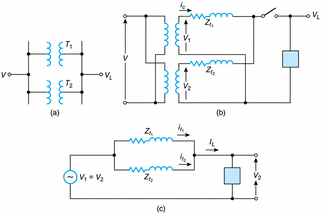
Figure 2-48 Two single-phase transformers in parallel. (a) One-line diagram. (b) Equivalent circuit for determining the circulating current. (c) Equivalent circuit for determining the load on each transformer. (The turns ratio for all units are assumed to be equal.)
In Figure 2-48(b), the load is disconnected from the common secondary transformer terminals, and thus this circuit can be used to find the transformer’s common circulating current. When the transformers have an equal number of winding turns, then Figure 2-48(c) may be used to find each transformer’s load as a function of the power delivered to the common load.
Transformers Must Have Equal Leakage Impedances
Assuming equal transformer voltage ratios, then from Figure 2-48(c), and by applying the current-divider concept, we obtain each transformer’s current as a function of the load current IL :
$$I_{t_1} = I_L \frac{Z_{t_2}}{Z_{t_1} + Z_{t_2}} \ \ \ \ \ (2.62)$$
And
$$I_{t_2} = I_L \frac{Z_{t_1}}{Z_{t_1} + Z_{t_2}} \ \ \ \ \ (2.63)$$
Where Zt1 and Zt2 are the leakage impedances of transformers 1 and 2, respectively.
From Equations (2.62) and (2.63), we obtain, when the leakage impedances are the same, that each transformer supplies half of the load current requirements. However, when the leakage impedances are unequal, the transformer currents are also unequal. As a result, the transformer that delivers the higher current may be overheated.
Transformers Must Have Equal Turns Ratios
When transformers are connected in parallel, their turns ratios must be equal. Otherwise, large no-load circulating currents will flow between the transformers.
From Figure 2-48(b), the circulating current is
$$I_c = \frac{V_1 - V_2}{Z_{t_1} + Z_{t_2}} \ \ \ \ \ (2.64)$$
where V1 and V2 are the voltages induced on the secondaries of transformers 1 and 2, respectively.
To minimize the circulating current, the “off-load” voltage tap changers should, if possible, be properly adjusted to equalize the voltages induced in the secondaries of the transformers.
If the transformers supply a load when their turns ratios are different, ordinary circuit-analysis techniques can be used to find the individual transformer currents.
Equal Phase Shift between the Voltages of Paralleled Units
The three-phase units must also produce secondary line-to-line voltages in phase when they are paralleled. Otherwise, large circulating currents will flow.
For this reason, a Δ - Y transformer cannot be paralleled with a Y-Y transformer. As previously mentioned, the line-to-line voltages on the delta side of a Δ - Y transformer lead the corresponding line-to-line voltages on the star side by 30°, while the line-to-line voltages on the primary of a star-star (Y-Y) transformer are in phase with the line-to-line voltages on the secondary side.
The line-to-line voltages for one phase only of a Δ - Y and Y-Y three-phase transformer are shown in Figures 2-49(a) and (b), respectively.
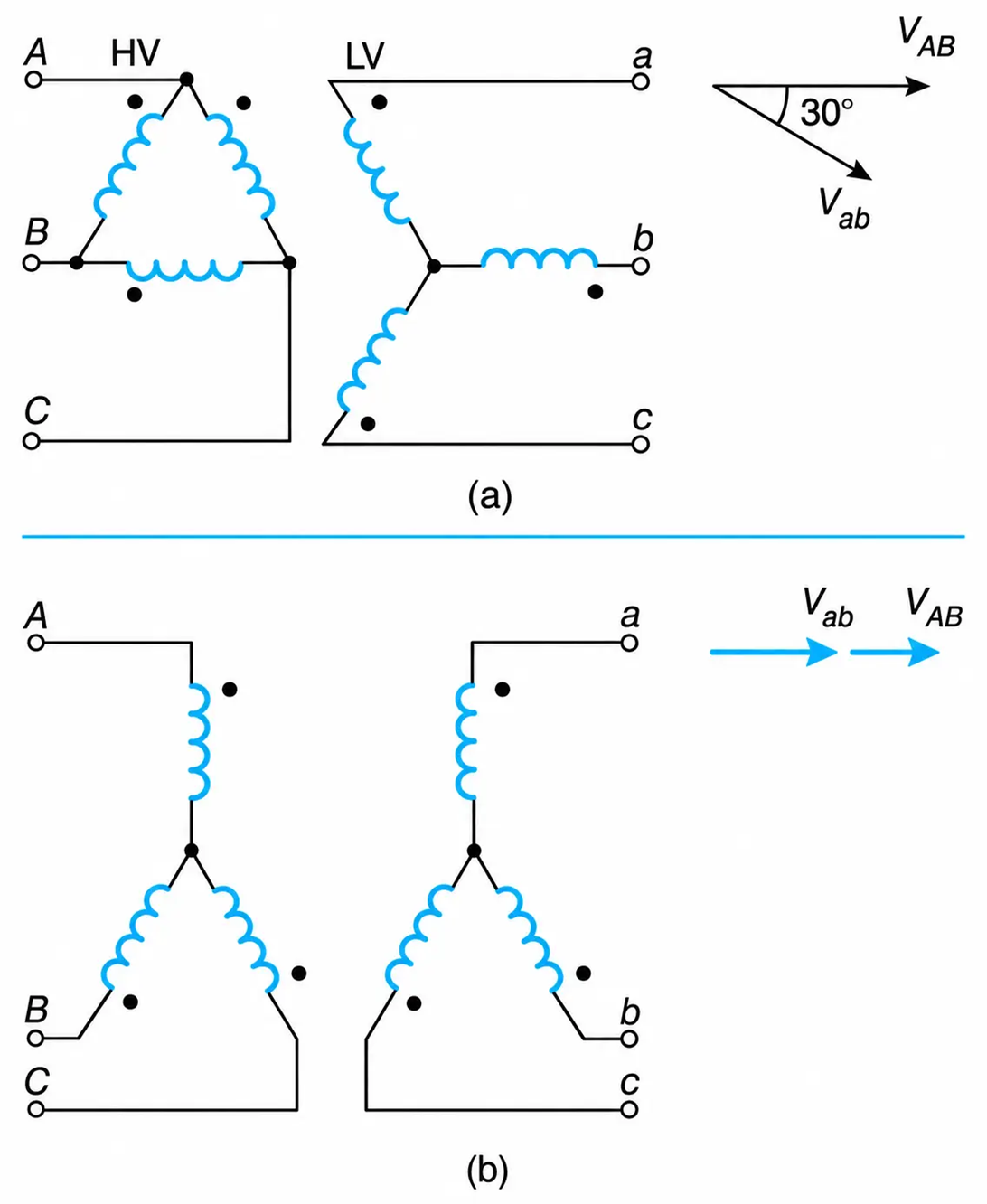
Figure 2-49 Two-winding, three-phase transformers and a partial voltage phasor diagram. (a) Delta–star. (b) Star–star.
Same Phase Rotation
When two transformers are paralleled, the primary and secondary voltages must have the same phase rotation. This condition is easily verified in the field, and if necessary, the connections of the two phases can be interchanged. This will result in the same phase rotation of the three-phase voltages. When the phase rotation is not the same, large circulating currents will flow through the transformer windings, and unbalanced voltages will be delivered to the load.
The paralleling of transformers, in general, results in higher rated and short-circuit currents through the common primary feeders. This, in turn, would require more expensive primary protective devices.
Circulating Currents
To prevent large circulating currents within the windings of the paralleled transformers, the following conditions must be satisfied.
- Equal winding leakage impedances.
- Equal winding turns ratio per phase.
- Equal phase shift of the secondary voltages.
Example 2-9
Two single-phase transformers are connected in parallel, as shown in Figure 2-50(a), and their primaries are connected to a 25 kV supply. The data on the nameplate of each transformer are as follows:
|
Transformer |
Rating in kVA |
Voltage Ratio |
Leakage Impedances in Per-Unit |
|
1 |
600 |
25,000–600 |
0.02 + j0.05 |
|
2 |
500 |
25,000–610 |
0.02 + j0.06 |
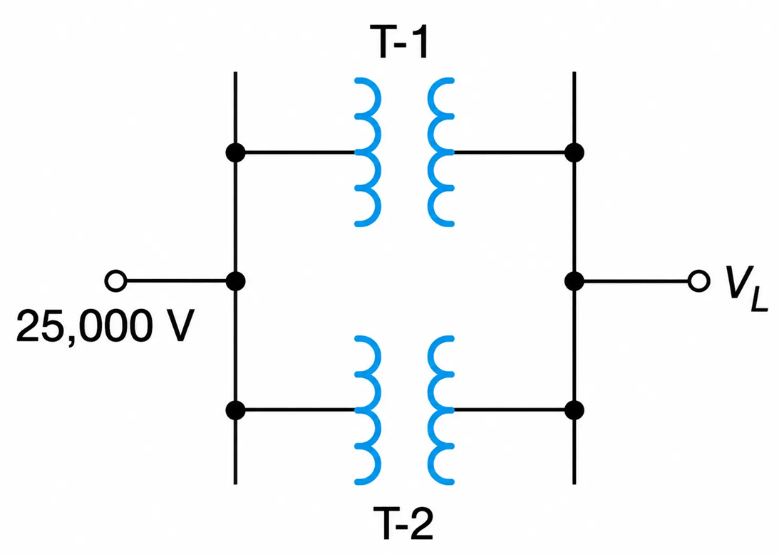
Figure 2-50 (a) Single-Phase Transformers Connected in Parallel
Determine:
a. The no-load circulating current.
b. The power loss due to the no-load circulating current.
Solution
a. Change the per-unit values of the transformer impedances to the equivalent ohmic values of the low-voltage winding.
For Transformer 1:
$$Z_{bL} = \frac{(600)^2}{600 \times 10^3} = 0.6\ \Omega$$
And
$$Z_{t_1} = (0.02 + j0.05)(0.6) = 0.012 + j0.03\ \Omega$$
For Transformer 2:
$$Z_{bL} = \frac{(610)^2}{500 \times 10^3} = 0.74\ \Omega$$
And
$$Z_{t_2} = (0.02 + j0.06)(0.74) = 0.015 + j0.045\ \Omega$$
Thus, from the equivalent circuit of Figure. 2-50(b), we have
$$I_c = \frac{V}{Z} = \frac{610 - 600}{0.012 + 0.015 + j(0.03 + 0.045)} = \frac{10}{0.027 + j0.075} = 125.95 \angle -70.2^\circ\ \text{A}$$
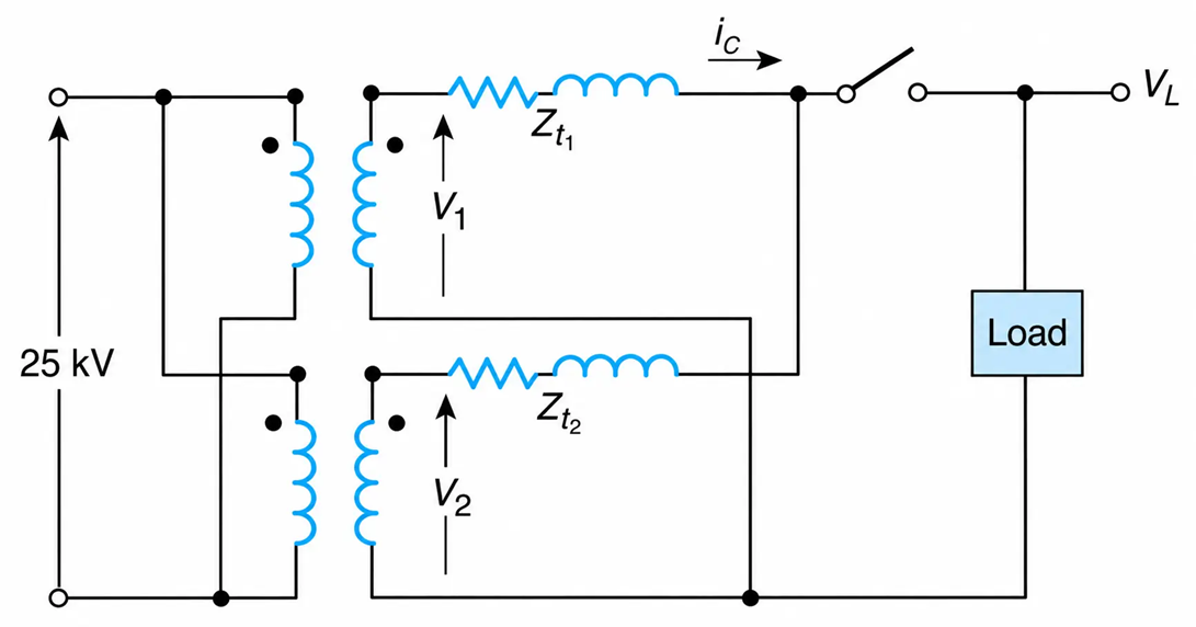
Figure 2-50 (b) Two single-phase transformers connected in parallel
b. The power loss due to circulating current is
$$I^2 R = (125.95)^2(0.027) = 426.73\ \text{W}$$
