Magnetic Field Intensity
The magnetic field intensity (H) for a given magnetic circuit is given by the ratio of the mmf divided by the length of the mean magnetic path. Thus,
$$\text{Magnetic field intensity}=\frac{\text{Ampere-turns}}{\text{Length of mean magnetic path}}$$
Using mathematical symbols,
$$H=\frac{Ni}{l} \qquad (1.107)$$
Considering incremental length changes, we have
$$Ni=\int H\,dl \qquad (1.108)$$
The unit of magnetic field intensity is
$$\frac{\text{ampere-turns}}{\text{meter}}\left(\frac{A}{m}\right)$$
$$1\,A/m=4\pi\times10^{-3}\,\text{oersteds}\,(Oe)$$
Magnetic field intensity is often referred to as magnetizing force.
Magnetic field intensity is related to flux density by
$$\mu=\frac{dB}{dH} \qquad (1.109)$$
where $\mu$ represents the permeability of the material.
Magnetic field intensity is used in the analysis of magnetic circuits. It is of unique importance in finding the voltage induced in a plane that is located at a given distance from a current-carrying conductor. The general expression for magnetic field intensity can be derived as follows. Consider Figure 1-53. The conductor carries current of amperes away from the reader into the plane of the paper.
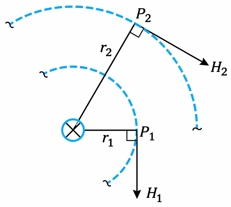
Figure 1-53 The concept of magnetic field intensity.
The conductor’s current produces a magnetic flux whose direction can be easily obtained from the right-hand rule. The mean magnetic paths of the flux at points P1 and P2 are given, respectively, by
$$I_{m1}=2\pi r_1 \qquad (1.110)$$
And
$$I_{m2}=2\pi r_2 \qquad (1.111)$$
From Equation (1.107), the magnetic field intensity at the points P1 and P2 is
$$H_1=\frac{i}{2\pi r_1} \qquad (1.112)$$
$$H_2=\frac{i}{2\pi r_2} \qquad (1.113)$$
The direction of the vector H1, as shown in the diagram, is perpendicular to the radius r1 at the point P1.
In general, the magnetic field intensity at a point P that is at a radius r from the center of the current-carrying conductor is
$$H=\frac{i}{2\pi r} \qquad (1.114)$$
The voltage induced in a plane is due only to the perpendicular component of the H on the plane under consideration.
Relationship between Electric and Magnetic Field Intensities
Starting from Maxwell’s equations, Poiynting showed that in free space the electric field intensity (E) is related to the magnetic field intensity (H) by the following equation.
$$E=nH \qquad (1.115)$$
where n is the impedance of space given by
$$n=\sqrt{\frac{\varepsilon_0}{\mu_0}} \qquad (1.116)$$
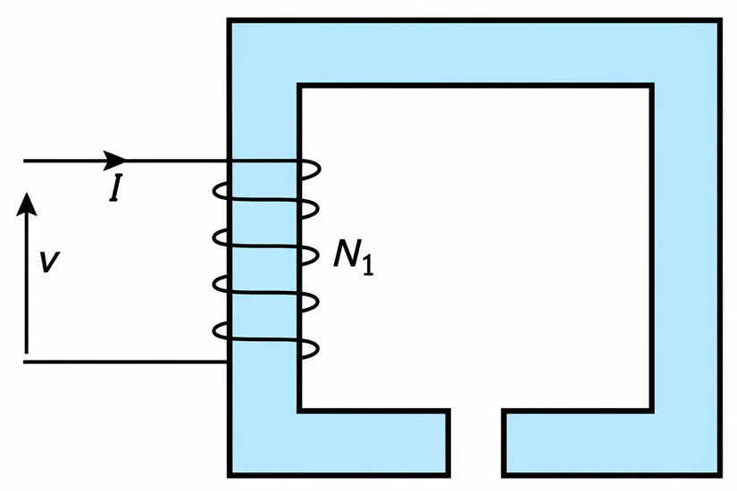
Figure 1-54 Electromagnet.
Substituting for the values of permittivity and permeability of free space, we obtain
$$n=377\,\text{ohms} \qquad (1.116a)$$
From above,
$$E=377H\,\text{V/m} \qquad (1.117)$$
In terms of flux density, we obtain
$$E=377\frac{B}{\mu} \qquad (1.118)$$
Measuring B in mG, we obtain
$$E=\frac{377}{4\pi\times10^{-7}}(10^{-3})(10^{-4})B \qquad (1.119)$$
And
$$E=30B\,\text{V/m} \qquad (1.120)$$
where B is in mG. That is,
$$\underline{\underline{1\,\text{mG}=30\,\text{V/m}}} \qquad (1.121)$$
Since it is relatively easy and inexpensive to measure B, calibrate such meters to indicate the electric field intensity.
Example 1-19
The mean magnetic path of the material shown in Figure 1-55 is 0.3 m, and its effective cross-sectional area is $5\times10^{-4}\,\text{m}^2$. The flux density is 0.007 T, and the dc resistance of the winding at the operating temperature is 2 ohms. Determine:
- The current drawn from the 24 V dc supply.
- The magnetic field intensity.
- The flux.
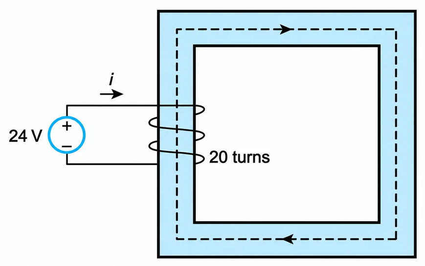
Figure 1-55 Magnetic Path
Solution
- $i=\frac{V}{R}=\frac{24}{2}=\underline{\underline{12\,A}}$
- $H=\frac{Ni}{l}=\frac{20(12)}{0.3}=\underline{\underline{800\,A/m}}$
- $\Phi=AB=5\times10^{-4}(0.007)=\underline{\underline{3.5\times10^{-6}\,Wb}}$
