Concept of Generated Voltage
A voltage can be induced in a conductor either by a time-varying magnetic field or as a result of a conductor’s motion in a stationary magnetic field. The first type is referred to as transformer voltage, the second as speed voltage.
The instantaneous value of each of these voltages will be designated, for the purpose of minimizing the symbol usage, by the same letter $\left(v\right)$.
Transformer Voltage
Refer to Figure 1-66. When a conductor is placed in a time-varying magnetic field, a voltage is induced in it. This voltage is commonly known as the transformer voltage. This voltage, first observed by Faraday, is given by
$$\upsilon=-N\frac{d\Phi}{dt} \qquad (1.137)$$
where $\left(v\right)$ is the instantaneous value of the voltage induced in the conductor, N is the number of the conductor’s turns, and $\frac{d\phi}{dt}$ is the time-rate of change of the magnetic flux. As per Lenz’s law, the minus sign in the equation indicates that the voltage induced is of a polarity that will produce a current whose flux opposes the flux that induced the voltage.
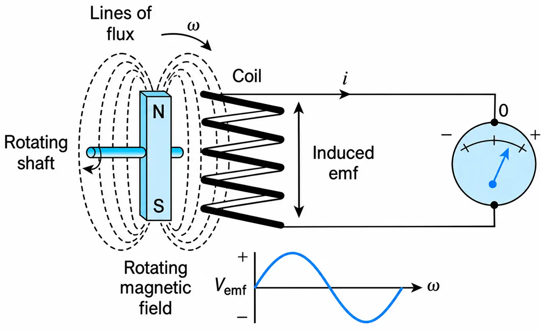
Figure 1-66 Rotating magnetic field and induced emf.
Equation (1.137) can also be written as
$$\upsilon = -\frac{d\lambda}{dt}\qquad (1.138)$$
where $\lambda$ is the conductor’s flux linkage.
Equations (1.137) and (1.138) both describe what is often referred to as the induction principle.
Example 1-22
a. Derive the expression for the voltage induced per unit length in the telephone lines shown in Figure 1-67(a). The single-conductor power line runs parallel to the telephone lines and carries a current given by $i=I_m\sin\omega t\ \text{A}$.
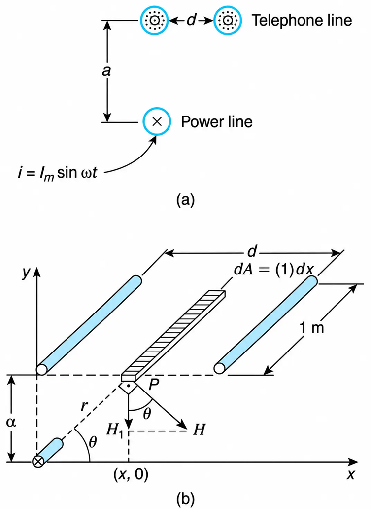
Figure 1-67 Voltage Induced in a Telephone Line
b. Evaluate the induced voltage, given that
$$I_m=1000\ \text{A}$$
$$\omega=377\ \text{rad/s}$$
$$\mu_0=4\pi\times10^{-7}\ \text{H/m}$$
$$\alpha=3\ \text{m}$$
$$d=0.5\ \text{m}$$
Solution
a. A voltage has meaning if it is specified between two points. In this example, the requirement is to find the voltage induced per unit length in the telephone lines. Rewriting the induction principle equation, we have
(I)
$$v=-N\frac{d\phi}{dt}$$
Thus the essential part of the problem is how to find the flux through the area between the telephone lines.
By definition,
(II)
$$\phi=\int B\,dA$$
where dA is an increment of area perpendicular to the flux. (The induced voltage depends on the component of the magnetic field perpendicular to the area between the telephone wires.)
For linear variation of flux density, we have
(III)
$$B=\mu H$$
Also,
(IV)
$$H=\frac{Ni}{l_m}$$
The number of turns is equal to unity, and the mean magnetic path at point P, shown in Figure 1-67(b), is
(V)
$$l_m=2\pi r$$
Thus,
$$H=\frac{i}{2\pi r}$$
Its component (H1), perpendicular to the area under consideration, is
(VI)
$$H_1=H\cos\theta=\left(\frac{i}{2\pi r}\right)\cos\theta$$
From the geometry of Figure 1-67(b), we obtain
(VII)
$$\cos\theta=\frac{x}{r}=\frac{x}{\sqrt{\alpha^2+x^2}}$$
From Equation (VI) and (VII), we get
(VIII)
$$H_1=\frac{i}{2\pi}\left(\frac{x}{\alpha^2+x^2}\right)$$
Then Equation (III) and (VIII) give
(IX)
$$B=\mu\frac{i}{2\pi}\left(\frac{x}{\alpha^2+x^2}\right)$$
Considering the shaded strip, we have
(X)
$$dA=(1)\,dx$$
The corresponding incremental flux through this element of area is
(XI)
$$d\phi=d(BA)=B\,dx$$
Substituting Equation (IX) into Equation (XI), we obtain
(XII)
$$d\phi=\mu\left[\frac{i}{2\pi}\left(\frac{x}{\alpha^2+x^2}\right)dx\right]$$
Taking the integrals, we find:
$$\phi=\mu\frac{i}{2\pi}\int_0^d\frac{x\,dx}{\alpha^2+x^2}$$
The variation of x or the limits of integration are from x = 0 to x = d. After integrating, we obtain
$$\phi=\left.\mu\frac{i}{2\pi}\left(\frac{1}{2}\right)\ln(\alpha^2+x^2)\right|_0^d$$
$$\phi=\frac{\mu}{4\pi}i\ln\left(\frac{\alpha^2+d^2}{\alpha^2}\right)$$
Substituting for the current, we get
$$\phi=\frac{\mu}{4\pi}\ln\left(\frac{\alpha^2+d^2}{\alpha^2}\right)I_m\sin\omega t$$
Taking the derivative of the flux with respect to time, and substituting the result into Equation (I), we obtain
$$v=-\frac{\mu}{4\pi}\ln\left(\frac{\alpha^2+d^2}{\alpha^2}\right)I_m\omega\cos\omega t\ \text{V/m}$$
b. Substituting the given values, we have
$$v=-\frac{4\pi\times10^{-7}}{4\pi}\ln\left(\frac{9+0.25}{9}\right)1000(377)\cos(377t)$$
$$v=-1.03\cos(377t)\ \text{mV/m}$$
Speed Voltage
The voltage induced in a conductor that moves through a stationary magnetic field (Figure 1-68) is referred to as the motional or speed voltage.
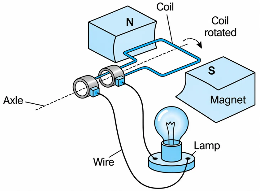
Figure 1-68 Generation of voltage.
Speed voltage $\left(v\right)$ is given by the following equation:
$$\upsilon=\int(\mathbf{U}\times\mathbf{B})\cdot dl \qquad (1.139)$$
where U × B is the cross product of the velocity and flux density vectors and dl, is a length element along the conductor.
When U, B, and l are perpendicular to each other, then Equation (1.139) is written as
$$\upsilon=BUl \qquad (1.140)$$
where B, U, and l are the magnitudes of the flux density, velocity, and length of the conductor, respectively.
Example 1-23
Figure 1-69(a) shows one coil turn of an ac generator that rotates at ω rad/s through a constant magnetic field of B tesla. Determine the voltage generated at the terminals of the generator if its coil has N turns connected in series.
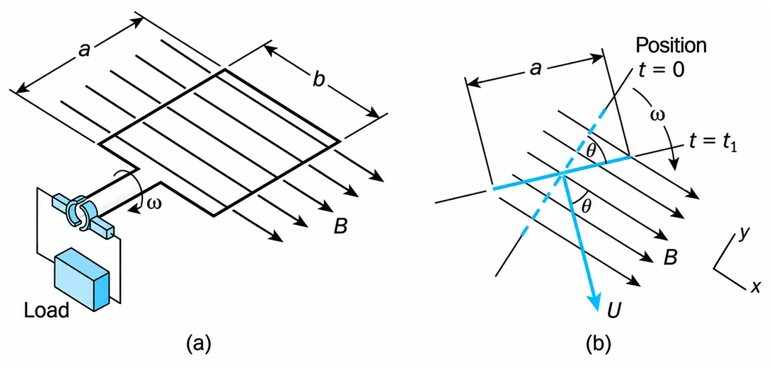
Figure 1-69 One Coil Turn of an AC Generator
Solution
Figure 1-69(b) shows the position of the conductor after it is rotated $\theta$ radians with respect to its position at t = 0. It should be noted that in the two sides of the conductor whose individual length is $\alpha$ meters, a voltage is induced, while in the other two sides of the conductor whose individual length is b meters, no voltage is induced. The area swept by each b-side of the conductor is parallel to the direction of the magnetic flux density; thus there is, in effect, no voltage induced in these two sides of the conductor.
The magnitude of the tangential component of the linear velocity is
$$U=\frac{b}{2}\omega \ \text{m/s}$$
In vector form,
$$\vec{U}=\frac{b}{2}\omega\left(\cos\theta\,\tilde{\alpha}_x-\sin\theta\,\tilde{\alpha}_y\right)$$
where $\tilde{\alpha}_x$ and $\tilde{\alpha}_y$ are the unit vectors in the x and y direction, respectively.
The flux density vector is
$$\overrightarrow{B}=B\tilde{\alpha}_x$$
The cross product of the velocity and flux density is
$$\overrightarrow{U}\times\overrightarrow{B}=\left|\begin{matrix}\tilde{\alpha}_x&\tilde{\alpha}_y&\tilde{\alpha}_z\\\omega\frac{b}{2}\cos\theta&-\omega\frac{b}{2}\sin\theta&0\\B&0&0\end{matrix}\right|=\frac{b}{2}\omega\tilde{\alpha}_z\left|\begin{matrix}\cos\theta&-\sin\theta\\B&0\end{matrix}\right|=\frac{b}{2}\omega B\sin\theta\,\tilde{\alpha}_z$$
Substituting the above into Equation (1.139), we obtain
$$\upsilon=\frac{b}{2}\omega B\sin\theta\int dl$$
The effective length of the conductor is 2a m. Thus,
$$\upsilon=abB\omega\sin\theta$$
Since $\theta = \omega t$ and the generator has N turns, the instantaneous value of the voltage generated is
$$\upsilon=abBN\omega\sin\omega t\ \text{V}$$
Voltage–Flux Relationship
When the coil of a magnetic circuit is connected to an AC voltage source, a current circulates. As a result, flux is produced. The equation that describes the flux generated as a function of the coil’s voltage is derived as follows.
Refer to the magnetic circuit in Figure 1-70. If losses are neglected, the voltage induced is equal to the applied voltage $(\upsilon_1)$. Assuming sinusoidal waveforms, we have
$$\upsilon_1=V_m\sin\omega t \qquad (1.141)$$
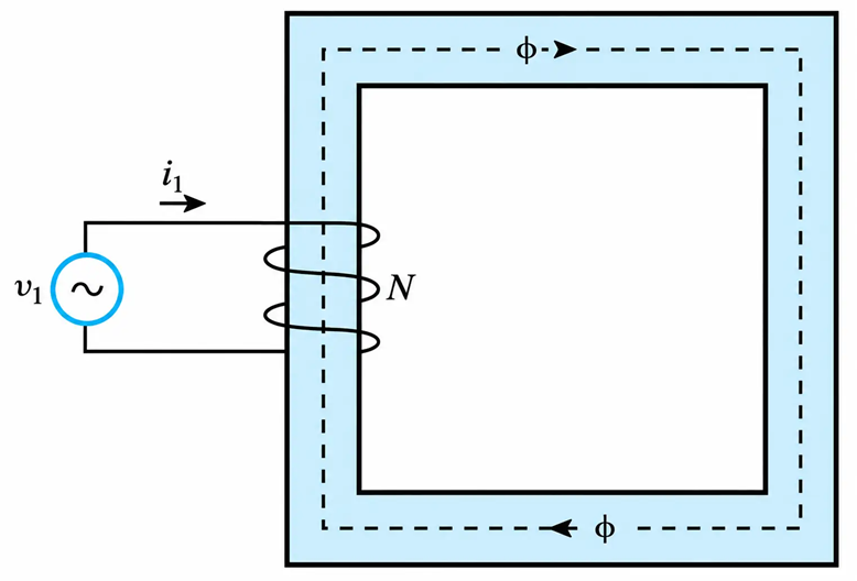
Figure 1-70 Magnetic circuit.
Equating the supply voltage and the voltage induced, we obtain
$$V_m\sin\omega t=-N\frac{d\Phi}{dt} \qquad (1.142)$$
from which
$$d\Phi=-\frac{1}{N}V_m\sin\omega t\,dt \qquad (1.143)$$
Integrating, we get
$$\Phi=\frac{V_m}{\omega N}\cos\omega t \qquad (1.144)$$
The flux, then, is a sinusoidal function whose maximum value is given by
$$\Phi_m=\frac{V_m}{\omega N} \qquad (1.145)$$
From the above,
$$V_m=2\pi fN\Phi_m \qquad (1.146)$$
Or
$$\sqrt{2}V=2\pi fN\Phi_m \qquad (1.147)$$
where V is the rms value of the applied voltage. From the last equation, we obtain
$$V=4.44Nf\Phi_m \qquad (1.148)$$
Equation (1.148) relates magnetic flux to applied electric volts and is of fundamental importance to the understanding of transformers and electric machines. This equation is often used to calculate the flux within a toroidal magnetic core.
Exercise
When the 40-turn coil of Figure 1-71 is connected to the 120 V, 60 Hz voltage supply, the voltages induced in the other coils are as shown. By neglecting leakage flux and winding losses, determine:
a. The number of turns of each coil.
$$\quad \frac{V_1}{V_2}=\frac{N_1}{N_2},\qquad \frac{120}{60}=\frac{40}{N_2},\qquad N_2=\underline{20\text{ turns}}$$
$$N_3=\frac{40(180)}{120}=\underline{60\text{ turns}}$$
b. The rms value of the mutual flux.
$$\phi=\frac{\phi_m}{\sqrt{2}}=\left(\frac{1}{\sqrt{2}}\right)\left(\frac{120}{4.44(40)(60)}\right)=\underline{7.96\text{ m Wb}}$$
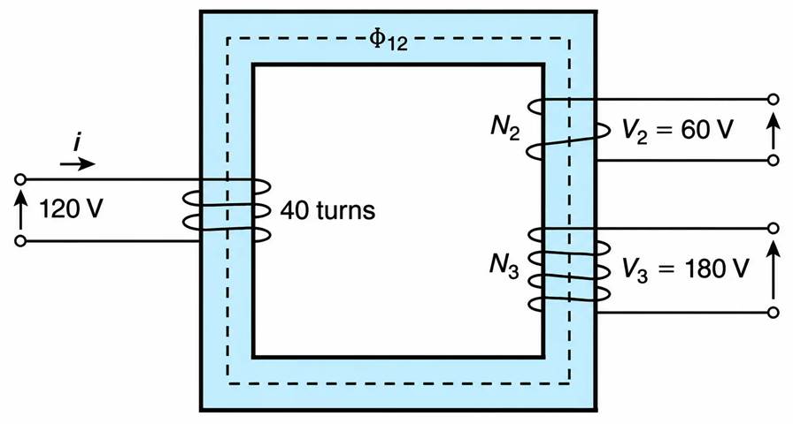
Figure 1-71 Magnetic Circuit with Coils
