Reluctance in Magnetism
The opposition to the flux in a given magnetic circuit is termed reluctance $(\mathcal{R})$. As in the case of the resistance of electric circuits, it is given by the ratio of the applied magnetic potential divided by the flux through the magnetic path under consideration. Mathematically,
$$\mathcal{R}=\frac{NI}{\Phi}\,\left(\frac{A}{Wb}\right) \qquad (1.132)$$
The reluctance of a magnetic path, being analogous to the resistance of an electric circuit, is also given by the following relationship:
$$\mathcal{R}=\frac{\ell}{\mu A} \qquad (1.133)$$
where $\ell$ is the length of the mean magnetic path, $\mu$ is the permeability of the material, and A is the material’s cross-sectional area perpendicular to the flux.
Reluctance, like electric resistance, varies with the impurity and temperature of the materials. Unsaturated magnetic materials have a relatively low reluctance because their permeability is thousands of times greater than that of the air.
The equivalent series or parallel reluctances of a magnetic circuit are calculated in the same way as the equivalent series or parallel resistances of an electric circuit. For example, the total reluctance of the magnetic circuit shown in Figure 1-64(b) is the sum of the reluctances of the magnetic material and of the air gap. That is,
$$\mathcal{R}_{\text{total}}=\mathcal{R}_{\text{magnetic material}}+\mathcal{R}_{\text{air gap}}=\mathcal{R}_m+\mathcal{R}_g \qquad (1.134)$$
$$\mathcal{R}_{\text{total}}=\frac{l_m}{\mu A}+\frac{l_g}{\mu_0 A} \qquad (1.135)$$
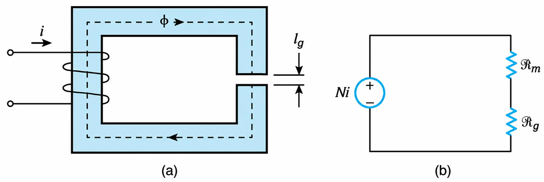
Figure 1-64 Electromagnet. (a) Physical representation. (b) Equivalent magnetic circuit.
Thus,
$$\mathcal{R}_{\text{total}}=\frac{1}{\mu_0 A}\left(\frac{l_m}{\mu_r}+l_g\right) \qquad (1.136)$$
As seen from Equation 1.136, the relative effect of the air gap on the magnetic circuit depends on how the length of the air gap compares to the ratio $\frac{l_m}{\mu_r}$ of the magnetic material.
The closed-loop property of magnetic flux and the concept of reluctance will be demonstrated by the following practical illustrations.
A Laboratory Case
In a laboratory, the arrangement shown in Figure 1-65(a) was used to measure the magnetic properties of E-type laminations as a function of temperature. Although the applied voltage to the coil was gradually increased to maximum, and the temperature of laminations was varied over a wide range, no reading could be obtained in the measuring bridge.
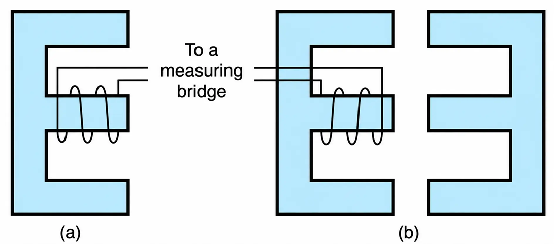
Figure 1-65 Illustrating the closed-loop property of magnetic flux: (a) Incorrect setup for measuring properties of magnetic materials. (b) Correct setup.
The mistake was that the setup used did not provide a path of low resistance to allow for the existence of flux. Owing to its large reluctance, air presents very high opposition to the flow of magnetic flux.
The problem was solved by rearranging the laminations as shown in Figure 1-65(b). In this case, magnetic materials were placed in the air path of the flux, and so the magnetic resistance was reduced a thousandfold. As a result, the quantity of flux through the coil increased. The measuring bridge then began to give readings that varied according to the ambient temperature and the applied voltage.
Demagnetizing the British Fleet
Refer to Figure 1-65(c). During the first phase of the Second World War, the German air force dropped magnetic mines in the navigated rivers and coastal waters of England. When a ship moved above a magnetic mine, the flux of its residual magnetism—a property of steel structure, closed its loop by penetrating through the mine. The movement of the ship was accompanied by a change of the flux through the magnetic mine, and thus a voltage was induced that triggered an explosion. In all, 37 allied ships were destroyed.
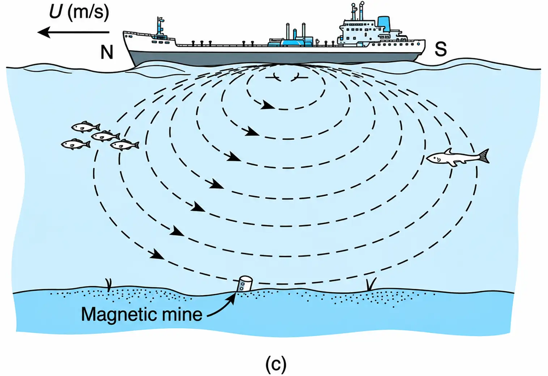
Figure 1-65 (c) The induction principle and the triggering of a magnetic mine.
The problem was solved by demagnetizing, or degaussing, the British Fleet. That is, flux of opposite direction and equal in strength to that produced by the ship’s residual magnetism was passed through the ship’s structure. As a result, the ship could not effectively emit any flux, and thus the magnetic mines remained untriggered. The neutralizing flux was generated by passing a specific amount of dc current through loops of wire properly wound around the ship.
Example 1-21
Determine the length of the air gap (Figure 1-64(a)) that will make its reluctance equal to that of the magnetic material. Assume that the cross-sectional areas are the same and that $l_m=0.60\,\text{m}$ and $\mu_r=1200$.
Solution
Rewriting the expression for the circuit reluctance, we have
$$\mathcal{R}=\frac{1}{\mu_0 A}\left(\frac{l_m}{\mu_r}+l_g\right)$$
In the above equation, the reluctance of the air gap will be equal to the reluctance of the magnetic material, provided that
$$\frac{l_m}{\mu_r}=l_g$$
Thus,
$$l_g=\frac{0.60}{1200}=\underline{\underline{0.5\,\text{mm}}}$$
